Return to Section TOC
Return to Section TOC
Return to Master TOC
Return to Master TOC
TROUBLESHOOTING & REPAIR
FLYWHEEL ALTERNATOR TEST (continued)
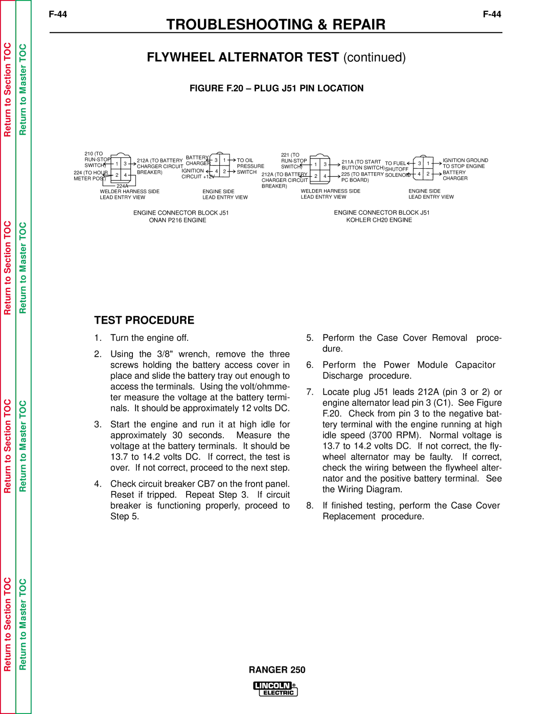
FIGURE F.20 – PLUG J51 PIN LOCATION
210 (TO |
|
|
| BATTERY |
|
|
| 221 (TO |
|
|
|
|
|
|
| |
|
| 212A (TO BATTERY | 3 | 1 | TO OIL |
|
| 211A (TO START |
|
|
| IGNITION GROUND | ||||
1 | 3 | CHARGER | 1 | 3 | TO FUEL | 3 | 1 | |||||||||
SWITCH) | CHARGER CIRCUIT |
|
| PRESSURE | SWITCH) | BUTTON SWITCH) | TO STOP ENGINE | |||||||||
|
|
| IGNITION | 4 | 2 |
|
| SHUTOFF |
|
| ||||||
224 (TO HOUR |
|
| BREAKER) | SWITCH | 212A (TO BATTERY |
|
| 225 (TO BATTERY | 4 | 2 | BATTERY | |||||
2 | 4 | 2 | 4 | SOLENOID | ||||||||||||
METER POS.) |
| CIRCUIT +12V |
|
|
| CHARGER | ||||||||||
|
|
|
|
|
| CHARGER CIRCUIT | PC BOARD) |
|
|
| ||||||
|
|
|
|
|
|
|
|
|
|
|
| |||||
|
|
|
|
|
|
|
|
|
|
|
|
|
| |||
| 224A |
|
|
|
|
| BREAKER) |
|
|
|
|
|
|
| ||
WELDER HARNESS SIDE | ENGINE SIDE | WELDER HARNESS SIDE | ENGINE SIDE |
LEAD ENTRY VIEW | LEAD ENTRY VIEW | LEAD ENTRY VIEW | LEAD ENTRY VIEW |
ENGINE CONNECTOR BLOCK J51 | ENGINE CONNECTOR BLOCK J51 | ||
| ONAN P216 ENGINE | KOHLER CH20 ENGINE |
|
Return to Section TOC
Return to Master TOC
TEST PROCEDURE
1.Turn the engine off.
2.Using the 3/8" wrench, remove the three screws holding the battery access cover in place and slide the battery tray out enough to access the terminals. Using the volt/ohmme- ter measure the voltage at the battery termi- nals. It should be approximately 12 volts DC.
3.Start the engine and run it at high idle for approximately 30 seconds. Measure the voltage at the battery terminals. It should be 13.7 to 14.2 volts DC. If correct, the test is over. If not correct, proceed to the next step.
4.Check circuit breaker CB7 on the front panel. Reset if tripped. Repeat Step 3. If circuit breaker is functioning properly, proceed to Step 5.
5.Perform the Case Cover Removal proce- dure.
6.Perform the Power Module Capacitor Discharge procedure.
7.Locate plug J51 leads 212A (pin 3 or 2) or engine alternator lead pin 3 (C1). See Figure F.20. Check from pin 3 to the negative bat- tery terminal with the engine running at high idle speed (3700 RPM). Normal voltage is 13.7 to 14.2 volts DC. If not correct, the fly- wheel alternator may be faulty. If correct, check the wiring between the flywheel alter- nator and the positive battery terminal. See the Wiring Diagram.
8.If finished testing, perform the Case Cover Replacement procedure.
Return to Section TOC
Return to Master TOC
