LOREX Technology QLR1660 Camera Installation, Audio & External Sensor/Relay Installation

Models: QLR1660

1 75
Download 75 pages 42.84 Kb
Page 9
Image 9
1.2 Camera Installation

DIGITAL VIDEO RECORDER

1.2 Camera Installation

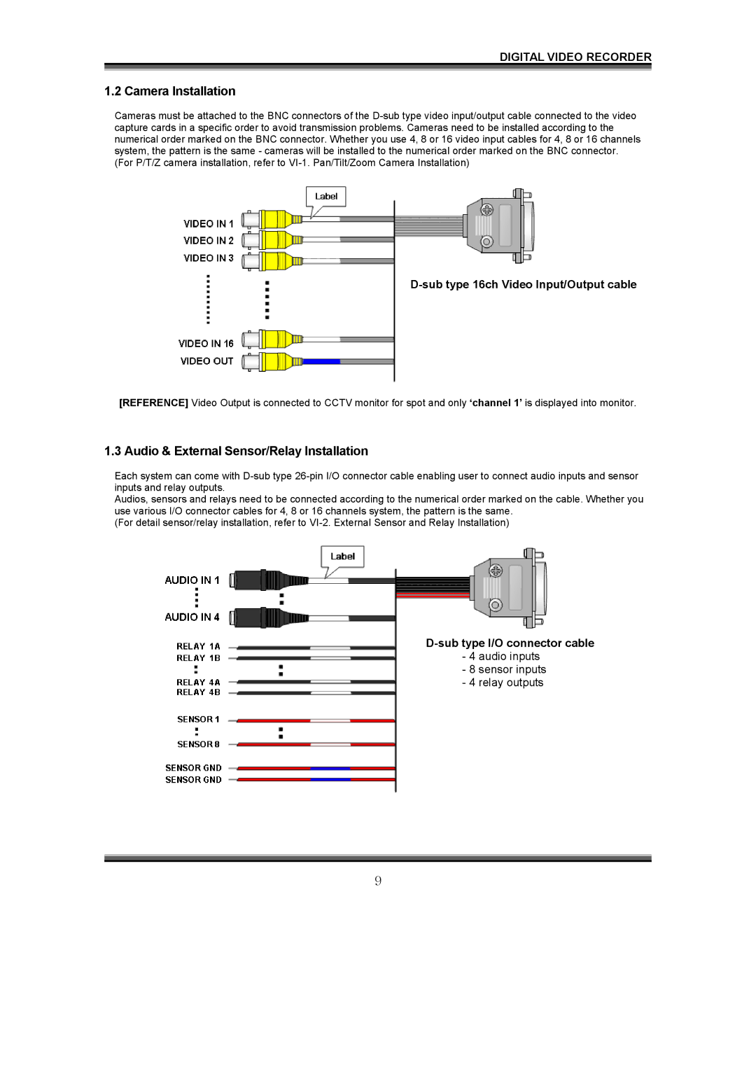
Cameras must be attached to the BNC connectors of the D-sub type video input/output cable connected to the video capture cards in a specific order to avoid transmission problems. Cameras need to be installed according to the numerical order marked on the BNC connector. Whether you use 4, 8 or 16 video input cables for 4, 8 or 16 channels system, the pattern is the same - cameras will be installed to the numerical order marked on the BNC connector. (For P/T/Z camera installation, refer to VI-1. Pan/Tilt/Zoom Camera Installation)

D-sub type 16ch Video Input/Output cable

[REFERENCE] Video Output is connected to CCTV monitor for spot and only ‘channel 1’ is displayed into monitor.

1.3 Audio & External Sensor/Relay Installation

Each system can come with D-sub type 26-pin I/O connector cable enabling user to connect audio inputs and sensor inputs and relay outputs.

Audios, sensors and relays need to be connected according to the numerical order marked on the cable. Whether you use various I/O connector cables for 4, 8 or 16 channels system, the pattern is the same.

(For detail sensor/relay installation, refer to VI-2. External Sensor and Relay Installation)

D-sub type I/O connector cable - 4 audio inputs

- 8 sensor inputs - 4 relay outputs

9

Page 9
Image 9
LOREX Technology QLR1660 Camera Installation, Audio & External Sensor/Relay Installation, sensor inputs - 4 relay outputs