Section 6 | Electrical System |
|
|
MOTOR SPEED SENSOR
Function
The motor speed sensor verifies that the gearbox motor is rotating at the correct speed.
Failure Modes
MOTOR SPEED SENSOR OPEN OR DISCONNECTED (ICE MACHINE WILL NOT START.)
Performs initial
MOTOR SPEED SENSOR CLOSED OR SHORTED (ICE MACHINE WILL NOT START.)
Performs initial
Check Procedure
1.Allow time for the evaporator to warm. Disconnecting power in the Freeze cycle will result in ice
2.Verify the motor speed sensor is in place and securely attached to the motor.
3.Verify the gearmotor run capacitor is functional.
4.Place toggle switch in the OFF position and place an identifying mark on the evaporator/gearbox coupling. This will provide a reference point to verify the coupler is rotating.
Move the toggle switch to the ICE position and verify the motor shaft and coupling are turning, then observe the Speed light.
(If the gear motor and coupling will not rotate, the switch is operating correctly.)
Speed light is: | Cause | |
|
| |
On | This is normal operation. | |
after 3 to 5 seconds | ||
| ||
|
| |
Off | Replace motor | |
speed sensor. | ||
| ||
|
| |
On after 3 to 5 seconds |
| |
and control board | Replace control board. | |
terminates Freeze cycle |
| |
|
|
To verify coupling/auger RPM (revolutions per minute):
1.Verify line voltage is within 10% of ice machine nameplate rating when low RPM is suspected.
2.Verify the gear motor run capacitor is functional.
3.Place identifying mark on coupling.
4.Count coupling revolutions for 2 minutes.
5.Divide coupling revolutions by 2 (example: 31 coupling revolutions ÷ 2 =
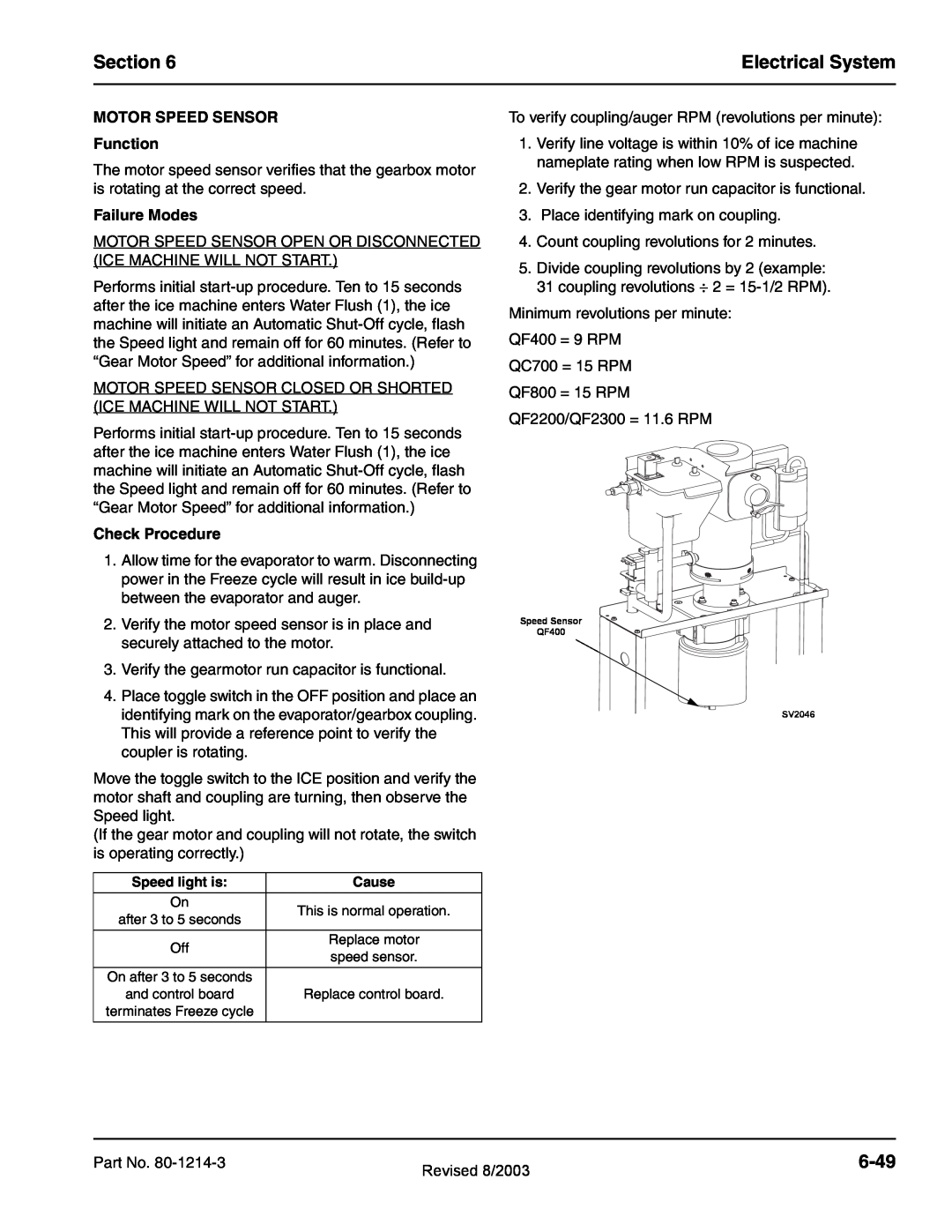
Minimum revolutions per minute:
QF400 = 9 RPM
QC700 = 15 RPM
QF800 = 15 RPM
QF2200/QF2300 = 11.6 RPM
Speed Sensor
QF400
SV2046
Part No. | Revised 8/2003 |
|
|
|