Section 6 | Electrical System |
|
|
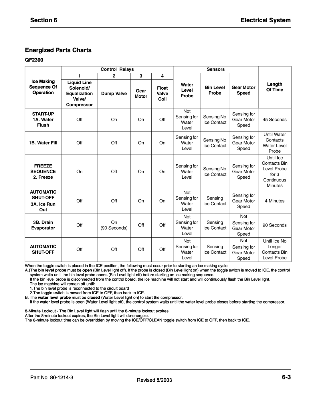
Energized Parts Charts
QF2300
|
| Control Relays |
|
|
| Sensors |
|
| |
|
|
|
|
|
|
|
|
|
|
| 1 | 2 |
| 3 | 4 |
|
|
|
|
Ice Making |
|
|
|
|
|
|
|
|
|
Liquid Line |
|
|
|
| Water |
|
| Length | |
Sequence Of | Solenoid/ |
|
|
| Float | Bin Level | Gear Motor | ||
|
| Gear | Level | Of Time | |||||
Operation | Equalization | Dump Valve |
| Valve | Probe | Speed | |||
| Motor | Probe |
| ||||||
| Valve/ |
|
| Coil |
|
|
| ||
|
|
|
|
|
|
|
| ||
| Compressor |
|
|
|
|
|
|
|
|
|
|
|
|
|
|
|
|
|
|
|
|
|
|
| Not |
| Sensing for |
| |
|
|
|
|
| Sensing for | Sensing No |
| ||
1A. Water | Off | On |
| On | Off | Gear Motor | 45 Seconds | ||
| Water | Ice Contact | |||||||
Flush |
|
|
|
|
| Speed |
| ||
|
|
|
|
| Level |
|
| ||
|
|
|
|
|
|
|
|
| |
|
|
|
|
|
|
|
|
|
|
|
|
|
|
|
| Sensing for |
| Sensing for | Until Water |
|
|
|
|
|
| Sensing No | Contacts | ||
1B. Water Fill | Off | Off |
| On | On | Water | Gear Motor | ||
| Ice Contact | Water Level | |||||||
|
|
|
|
|
| Level | Speed | ||
|
|
|
|
|
|
| Probe | ||
|
|
|
|
|
|
|
|
| |
|
|
|
|
|
|
|
|
|
|
|
|
|
|
|
|
|
|
| Until Ice |
FREEZE |
|
|
|
|
| Sensing for |
| Sensing for | Contacts Bin |
|
|
|
|
| Sensing No | Level Probe | |||
SEQUENCE | On | Off |
| On | On | Water | Gear Motor | ||
| Ice Contact | for 3 | |||||||
2. Freeze |
|
|
|
|
| Level | Speed | ||
|
|
|
|
|
| Continuous | |||
|
|
|
|
|
|
|
|
| |
|
|
|
|
|
|
|
|
| Minutes |
|
|
|
|
|
|
|
|
|
|
AUTOMATIC |
|
|
|
|
| Not |
| Sensing for |
|
|
|
|
|
| Sensing for | Sensing |
| ||
Off | Off |
| On | On | Gear Motor | 4 Minutes | |||
3A. Ice Run |
| Water | Ice Contact | ||||||
|
|
|
|
| Speed |
| |||
Out |
|
|
|
|
| Level |
|
| |
|
|
|
|
|
|
|
| ||
|
|
|
|
|
|
|
|
|
|
|
|
|
|
|
| Not |
| Not |
|
3B. Drain | Off | On |
| Off | Off | Sensing for | Sensing | Sensing for | 90 Seconds |
Evaporator | (90 Seconds) |
| Water | Ice Contact | Gear Motor | ||||
|
|
|
|
| |||||
|
|
|
|
|
| Level |
| Speed |
|
|
|
|
|
|
|
|
|
|
|
|
|
|
|
|
| Not |
| Not | Until Ice No |
AUTOMATIC | Off | Off |
| Off | Off | Sensing for | Sensing | Sensing for | Longer |
| Water | Ice Contact | Gear Motor | Contacts Bin | |||||
|
|
|
|
| |||||
|
|
|
|
|
| Level |
| Speed | Level Probe |
|
|
|
|
|
|
|
|
|
|
When the toggle switch is placed in the ICE position, the following must occur prior to starting an ice making cycle.
A.)The bin level probe must be open (Bin Level light off). If the probe is closed (Bin Level light on) when the toggle switch is moved to ICE, the control system waits until the bin level probe opens (Bin Level light off) before starting an ice making sequence.
If the bin level probe is disconnected from the control board, the ice machine will not start and will continuously flash the Bin Level light. The ice machine will remain off until:
1.The bin level probe is reconnected to the circuit board
2.The toggle switch is moved from ICE to OFF, then back to ICE.
B. The water level probe must be closed (Water Level light on) to start the compressor.
If the water level probe is open (Water Level light off), the control system waits until the water level probe closes before starting the compressor.
The
Part No. | Revised 8/2003 | |
|
|