Electrical System | Section 6 |
|
|
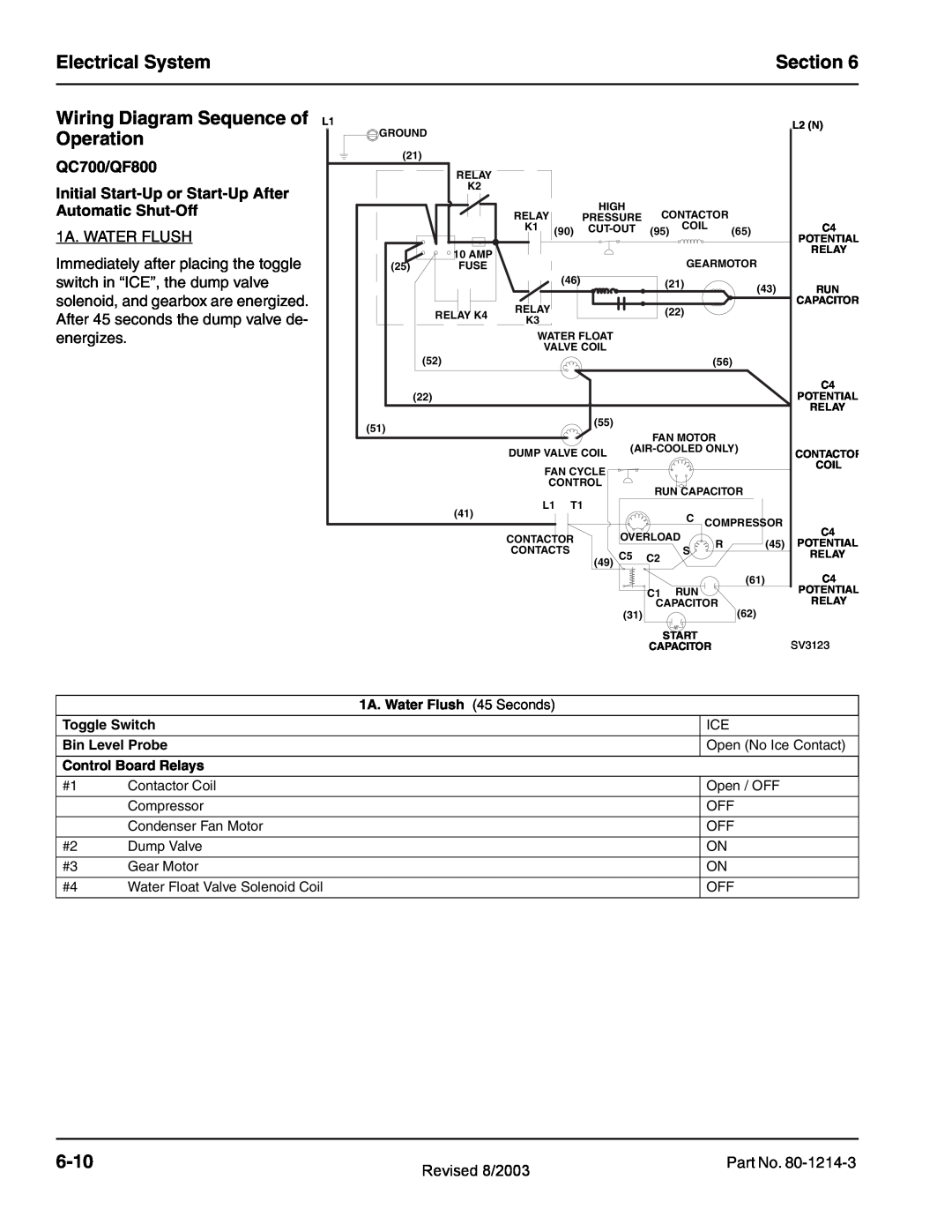
Wiring Diagram Sequence of L1 Operation
QC700/QF800
Initial
1A. WATER FLUSH
Immediately after placing the toggle switch in “ICE”, the dump valve solenoid, and gearbox are energized. After 45 seconds the dump valve de- energizes.
GROUND |
|
|
|
|
|
|
|
|
|
| L2 (N) |
|
|
|
|
|
|
|
|
|
|
| |
(21) |
|
|
|
|
|
|
|
|
|
|
|
| RELAY |
|
|
|
|
|
|
|
|
|
|
| K2 |
|
|
|
|
|
|
|
|
|
|
|
| RELAY |
| HIGH | CONTACTOR |
|
| ||||
|
|
| PRESSURE |
|
| ||||||
|
| K1 | (90) | (95) | COIL | (65) | C4 | ||||
|
|
|
|
|
|
|
|
|
|
| POTENTIAL |
| 10 AMP |
|
|
|
|
|
|
|
|
| RELAY |
|
|
|
|
|
|
| GEARMOTOR |
| |||
(25) | FUSE |
|
|
|
|
|
|
| |||
|
|
|
| (46) |
|
| (21) |
| (43) | RUN | |
|
|
|
|
|
|
|
| ||||
|
|
|
|
|
|
|
|
|
| ||
|
| RELAY |
|
|
| (22) |
|
| CAPACITOR | ||
| RELAY K4 |
|
|
|
|
|
| ||||
| K3 |
|
|
|
|
|
|
|
|
| |
|
|
|
|
|
|
|
|
|
|
| |
|
| WATER FLOAT |
|
|
|
|
|
| |||
|
|
| VALVE COIL |
|
|
|
|
|
| ||
(52) |
|
|
|
|
|
|
| (56) |
| ||
|
|
|
|
|
|
|
|
|
|
| C4 |
(22) |
|
|
|
|
|
|
|
|
|
| POTENTIAL |
|
|
|
|
|
|
|
|
|
|
| RELAY |
(51) |
|
|
|
| (55) |
|
|
|
|
|
|
|
|
|
|
|
| FAN MOTOR |
|
| |||
|
|
|
|
|
|
|
|
| |||
|
| DUMP VALVE COIL | CONTACTOR | ||||||||
|
|
|
|
|
|
| |||||
|
|
| FAN CYCLE |
|
|
|
|
| COIL | ||
|
|
|
|
|
|
|
|
| |||
|
|
| CONTROL |
| RUN CAPACITOR |
| |||||
|
|
|
|
|
|
|
| ||||
| (41) |
| L1 | T1 |
|
|
|
|
|
| |
|
|
|
|
|
|
| C | COMPRESSOR |
| ||
|
|
|
|
|
|
|
| C4 | |||
|
| CONTACTOR |
| OVERLOAD |
|
| |||||
|
|
| R | (45) | POTENTIAL | ||||||
|
| CONTACTS |
|
|
| S | |||||
|
| (49) | C5 | C2 |
|
| RELAY | ||||
|
|
|
|
|
|
|
| ||||
|
|
|
|
|
|
|
|
|
|
| |
|
|
|
|
|
|
|
|
|
| (61) | C4 |
|
|
|
|
|
|
| C1 | RUN |
|
| POTENTIAL |
|
|
|
|
|
| (31) | CAPACITOR | (62) | RELAY | ||
|
|
|
|
|
|
|
|
|
| ||
|
|
|
|
|
|
| START |
|
| SV3123 | |
|
|
|
|
|
|
| CAPACITOR |
| |||
|
| 1A. Water Flush (45 Seconds) | |
|
|
| |
Toggle Switch |
| ICE | |
|
|
| |
Bin Level Probe |
| Open (No Ice Contact) | |
|
|
| |
Control Board Relays |
|
| |
|
|
|
|
#1 | Contactor Coil |
| Open / OFF |
|
|
|
|
| Compressor |
| OFF |
|
|
|
|
| Condenser Fan Motor |
| OFF |
|
|
|
|
#2 | Dump Valve |
| ON |
|
|
|
|
#3 | Gear Motor |
| ON |
|
|
|
|
#4 | Water Float Valve Solenoid Coil |
| OFF |
|
|
|
|
| Revised 8/2003 | Part No. |
|
|