Electrical System | Section 6 |
|
|
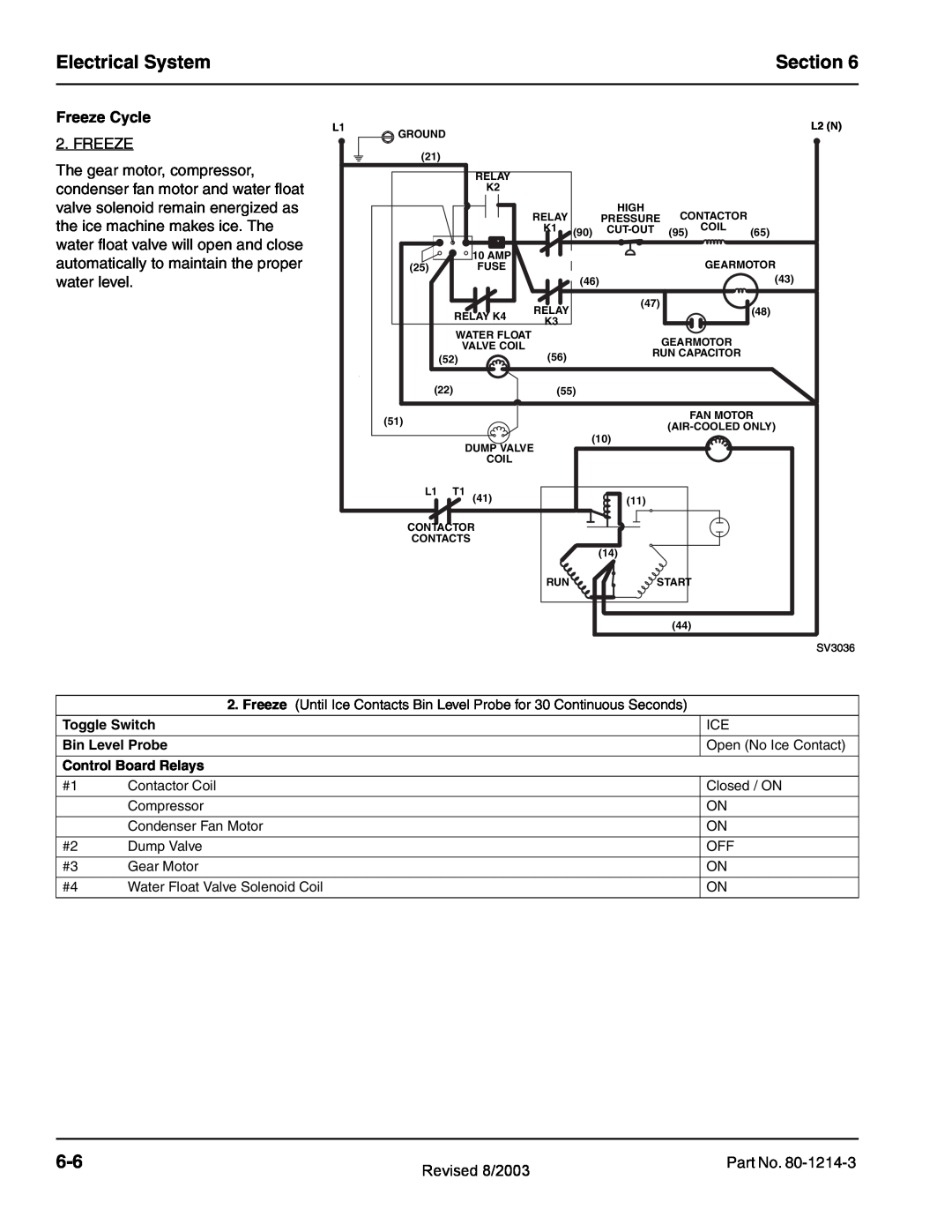
Freeze Cycle
L1
2. FREEZE
The gear motor, compressor, condenser fan motor and water float valve solenoid remain energized as the ice machine makes ice. The water float valve will open and close automatically to maintain the proper water level.
L2 (N)
![]() GROUND
GROUND
(21) |
|
|
|
|
|
|
|
| RELAY |
|
|
|
|
|
|
| K2 |
|
|
|
|
|
|
|
| RELAY |
| HIGH | CONTACTOR |
| |
|
|
| PRESSURE |
| |||
|
| K1 | (90) | (95) | COIL | (65) | |
| 10 AMP |
|
|
|
| GEARMOTOR | |
(25) | FUSE |
|
|
|
| ||
|
|
| (46) |
|
|
| (43) |
|
| RELAY |
| (47) |
|
| (48) |
RELAY K4 |
|
|
|
| |||
K3 |
|
|
|
|
| ||
|
|
|
|
|
|
| |
WATER FLOAT |
|
|
| GEARMOTOR |
| ||
| VALVE COIL |
|
|
|
| ||
| (56) |
| RUN CAPACITOR |
| |||
(52) |
|
|
| ||||
|
|
|
|
|
| ||
(22) |
| (55) |
|
|
|
| |
(51) | FAN MOTOR | |
|
(10)
DUMP VALVE
COIL
L1 | T1 | (41) | (11) |
CONTACTOR |
| ||
CONTACTS |
|
| |
(14)![]()
RUN ![]() START
START
(44)
SV3036
2. Freeze (Until Ice Contacts Bin Level Probe for 30 Continuous Seconds)
Toggle Switch
Bin Level Probe
Control Board Relays
#1 Contactor Coil
Compressor
Condenser Fan Motor
#2 Dump Valve
#3 Gear Motor
#4 Water Float Valve Solenoid Coil
ICE
Open (No Ice Contact)
Closed / ON
ON
ON
OFF
ON
ON
Revised 8/2003 | Part No. | |
|
|