Electrical System | Section 6 |
|
|
Wiring Diagram Sequence of L1 Operation
QF2200
Initial
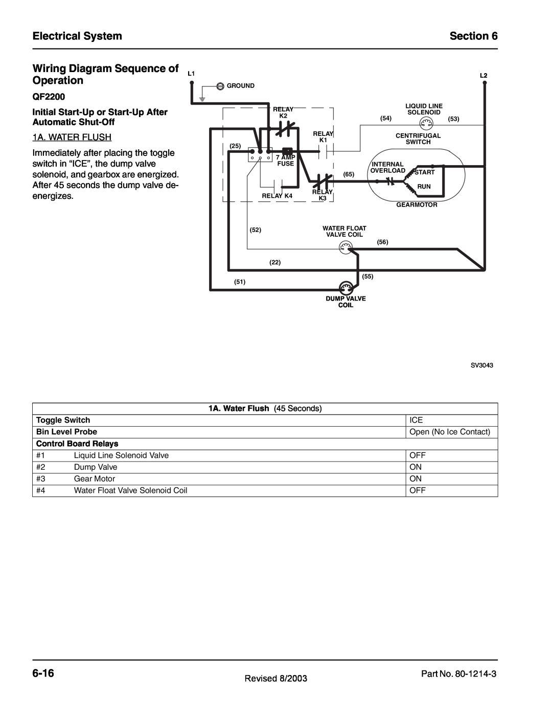
1A. WATER FLUSH
Immediately after placing the toggle switch in “ICE”, the dump valve solenoid, and gearbox are energized. After 45 seconds the dump valve de- energizes.
|
|
|
| L2 |
GROUND |
|
|
|
|
RELAY |
|
| LIQUID LINE |
|
|
| SOLENOID |
| |
K2 |
| (54) | (53) | |
|
| |||
|
|
| ||
| RELAY | CENTRIFUGAL |
| |
| K1 |
| ||
(25) |
| SWITCH |
| |
|
|
| ||
|
|
|
| |
7 AMP |
|
|
|
|
FUSE |
| INTERNAL |
|
|
| (65) | OVERLOAD | START |
|
|
|
| ||
|
|
|
| |
| RELAY |
| RUN |
|
RELAY K4 |
|
|
| |
K3 |
|
|
| |
| GEARMOTOR |
| ||
|
|
| ||
(52) | WATER FLOAT |
|
|
|
| VALVE COIL | (56) |
|
|
|
|
|
| |
(22) |
|
|
|
|
(51) | (55) |
|
| |
|
|
|
| |
| DUMP VALVE |
|
|
|
| COIL |
|
|
|
|
|
|
| SV3043 |
|
| 1A. Water Flush (45 Seconds) | |
|
|
| |
Toggle Switch |
| ICE | |
|
|
| |
Bin Level Probe |
| Open (No Ice Contact) | |
|
|
| |
Control Board Relays |
|
| |
|
|
|
|
#1 | Liquid Line Solenoid Valve |
| OFF |
|
|
|
|
#2 | Dump Valve |
| ON |
|
|
|
|
#3 | Gear Motor |
| ON |
|
|
|
|
#4 | Water Float Valve Solenoid Coil |
| OFF |
|
|
|
|
| Revised 8/2003 | Part No. |
|
|