SR7005
Page
Important Notice do not Modify this Product
Surface CHAUDE. NE PAS Toucher
Superficie CALIENTE. no Tocar
Compliance Information
Avertissements Advertencias
Getting started
Contents
About this manual
Accessories
Features
Speaker terminal for front height channel
Other features
Direct play for iPod and iPhone via USB
XPort Marantz-eXtension Port
Detection
Set up speakers Audyssey Auto Setup
Vpage
Preparation Speaker Measurement Calculation Check Store
Speaker terminals Impedance
Connecting the speaker cables
Speakers
Built-in amplifier
Blu-ray Disc player and TV
Blu-ray Disc player
Subwoofer with
Set up speakers
About the main listening position *M
About setup microphone placement
Set up the subwoofer
Set up the remote control unit
Preparation
When performing Audyssey Auto Setup over again
When measuring has stopped
Setting up the speakers again
Calculation Check Store
Nn When turning Dynamic Volume on
Nn When turning Dynamic Volume off
Finish
Press Return
Retrieving Audyssey Auto Setup settings
Examples Error details
Set the listening mode
When power is switched to standby
Adjust the sound volume
For speaker connections, see
Basic version
Important information
GFlow of video signals for ZONE2H
GFlow of video signals for Main Zoneh
Connections
Connecting an HDMI-compatible device
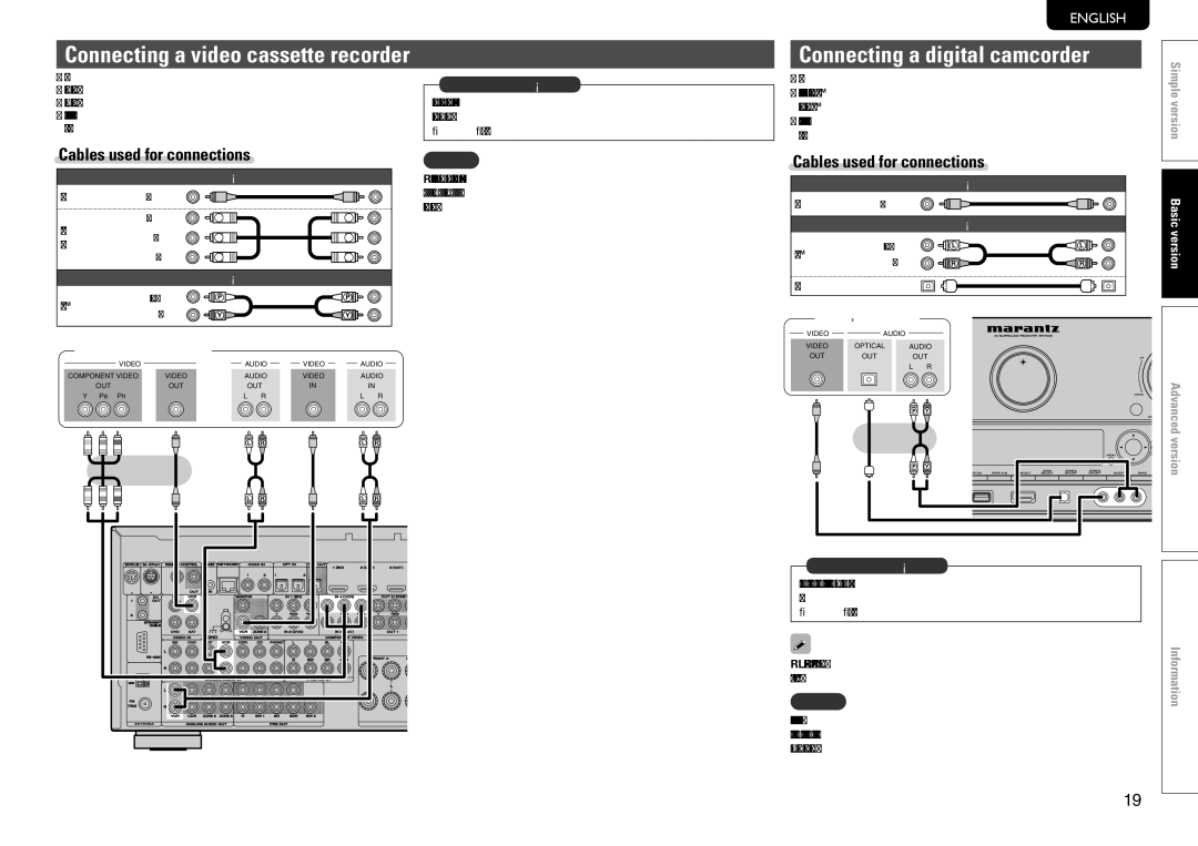
Cables used for connections
Connecting to a device equipped with a DVI-D connector
NnSettings related to Hdmi connections
Hdmi Setup vpage
Cables used for connections
Connecting a TV
Connecting a Blu-ray Disc player
Digital cable DVD player
Connecting a DVD player
Connecting a set-top box Satellite tuner/cable TV
Coaxial
Optical cable Digital camcorder Video cassette recorder
Connecting a digital camcorder
Compatible device vpage
Optical cable CD player
Supported iPod models
You can enjoy music stored on an iPod or USB memory device
USB
You can enjoy playing records
Connecting a CD recorder
Connecting a record player
Optical cable CD recorder
NnPositioning the antenna
Connecting an antenna
Connecting a Sirius connector
Connecting an HD Radio receiver
Standing alone
Connecting a wireless receiver RX101
NnAM loop antenna assembly
NnUsing the AM loop antenna Suspending on a wall
Connect a device that has a multichannel output terminal
Connecting a external power amplifier
Audio cable Power amplifier
NnEthernet cable CAT-5 or greater recommended
Required system
NnBroadband internet connection nnModem
NnRouter
Playback Basic operation
NnUsing the Source Select menu
NnUsing the button on the remote control unit
NnUsing the knob on the main unit
Set the front speakers to be used
Adjusting the master volume
Playing a Blu-ray Disc player/DVD player
Playing a CD player
Use ui to select iPod, then press Enter or p
Direct mode
Display mode
Playing an iPod
Important information
Playing a USB memory device
Uio p
Playing files stored on USB memory devices
NnUSB operation
Press ui to select USB, then press Enter or p
NnAbout Sirius XM radio
Tuning in radio stations
NnUsing the HD Radio receiver
Listening to Sirius satellite radio
NnSearching categories
NnPresetting radio channels Preset memory
NnListening to preset channels
NnAccessing Sirius satellite radio channels directly
NnSIRIUS operation
Listening to HD Radio stations
NnParental Lock
NnSelecting audio programs
NnPresetting radio stations Manual preset
Default settings
NnDirect frequency tuning
NnMedia player
Playing a network audio
NnTuner HD Radio reception operation
NnAbout the internet radio function
NnRecently played internet radio stations
Listening to internet radio
NnAbout Flickr NnAbout Napster NnAbout Pandora
NnAbout Rhapsody
NnRegistering internet radio stations as your favorites
NnPresetting internet radio stations
NnListening to preset internet radio stations
Press SHIFT/TOP MENU, then press Preset +, Preset or
NnInternet radio operation
Playing files stored on a computer
Pressor p. ui to select the file, and then press Enter
NnMedia server operation
NnViewing photographs shared by particular users
Pressor p.uito select the folder, and then press Enter
NnFlickr operation
Next To cancel, press ui or SEARCH/INFO
Listening to Napster
NnViewing all photographs on Flickr
Listening to tracks registered in my Napster library
NnSearching from Napster menu
NnRegistering tracks in my Napster library
NnNapster operation
NnCreating an original radio station
Listening to Pandora
NnPandora operation
NnArranging tracks within radio stations
NnSign out
Listening to created radio stations at random
Search from the Rhapsody internet radio station
NnSelect the search mode
Listening to Rhapsody
Search from Rhapsody latest information
Rating function
NnTrack menu
Search from the similar music
Registering tracks in my library
NnSurround playback of 2-channel sources
Selecting a listening mode Surround mode
Listening mode
Multi-channel playback
GViews on the displayH
Displaying the currently playing surround mode
Input signal Surround mode Display
Direct playback
NnDolby Virtual Speaker mode
NnDolby Headphone mode
Stereo playback
Advanced version
Install
Speaker installation/connection Advanced connection
Install
When 6.1ch Surround back speaker installed
For speaker impedance and speaker cable connections, see
When 5.1ch installed
When Front A/B speakers installed
Channel Surround back speaker connection Channel connection
Bi-Amp connection
NnFor connecting two subwoofers
Front A/B connection
Set up
Set up speakers
Set up Amp Assign
Set up Channel Select
NnConnection
Remote Control jacks
NnSetting
Connections Advanced connection
Trigger Out 1 or Trigger Out 2 vpage
RS-232C connector
DC OUT Trigger OUT jacks
Hdmi control function
Nn Adjusting the volume of the speakers vpage
Playback Advanced operation
Convenient functions
NnAdjusting the volume of groups of speakers Fader function
Sleep timer function
Adjusting the volume of the speakers
To cancel the sleep timer
NnPlaying contents on a mobile terminal device
NnPlaying content on a computer Media server
VGExample 3H
Web control function
Enterbox. the IP address of this unit in browser’s address
Operate
GExample 6H Dedicated iPod Touch screen
GExample 2H Setup menu screen
Various memory functions
Panel lock function
NnAudio connections ZONE2, ZONE3
NnConnecting and setting the speakers
Playback in ZONE2/ZONE3 Separate room
Audio output
Video Connection
Adjusting the volume
Video output
Playback
Items that only need to be set Once
How to make detailed settings
Menu map
Examples of menu and front display
Display when inputting characters
Display when resetting
Normal screen
Inputting characters
Keyboard screen
Select a character to be input with uio p then press Enter
Input Setup
Menu operation
NnAbout the display of input sources
Parental Lock
Auto Preset
Preset Skip
Items that can be set with the Input Setup procedure
Examples of input assign menu screen displays
Preset Name
Input Assign
Antenna Aiming
CDR
Hdmi
DVD VCR
DVD VCR SAT
SAT AUX1 DVD VCR
AUX1
Source Level
Input Mode
Playback Mode
Rename
Nn Audio Delay vpage Picture Adjust vpage
Audio/Video Adjust
Items that can be set with the Audio/Video Adjust procedure
Audio Adjust vpage Nn Surround Parameter vpage
NnTone
Audio Adjust
NnSurround Parameter
Press DYN EQ/VOL
NnAudyssey Settings
Setting items Setting details MultEQ XT
Setting items Setting details Dynamic EQ
About Audyssey Dynamic Surround Expansion A-DSX
Setting items Setting details Dynamic Volume
Setting items Setting details Audyssey DSX
NnM-DAX
NnAudio Delay
DVD VCR SAT Game AUX1 NET/USB TV
Manual Setup
Picture Adjust
Items that can be set with the Manual Setup procedure
Setting items Setting details Speaker Config
Speaker Setup
Setting items Setting details Amp Assign
Channel Level
Bass Setting
12.0dB +12.0dB 0.0dB Adjust the volume
Distance
Hdmi Setup
EQ Customize
Audio Setup
Setting items Setting details Standby Source
1ch in SW Level
Other
Setting items Setting details Network Connecting
HPF
GUI
Option Setup
Using Source SEL
BD / DVD / VCR / SAT / Game / AUX1 / NET/USB
Nn When setting for Hdmi monitor
Nn When setting for zone Main Zone / ZONE2 / ZONE3
Nn When setting for input source
Maintenance Mode
Setting items Setting details Display
Setup Lock
Setting items Setting details Firmware Update
Svenska Nederlands Español Italiano Français Deutsch English
Nn ZONE3
Information
Nn Main Zone
Nn ZONE2
NnEnabling the remote sensor function
Other settings
Remote control settings
NnDisabling the sensor function of the remote control unit
Press the input source select button vpage
Operating the connected devices by remote control unit
Operating AV equipment
Check the registered preset code
Registering preset codes
Registering preset codes
NnCD player / CD recorder operation
Default settings for preset codes
Switch the input source vpage Operate the component
Operating components
NnSet top box for satellite SAT operation
Remembering remote control codes from other devices
Operating learn function
Input source is shown in the remote control display
Delete saved remote control codes
NnDelete remote control codes for each input source
NnDelete remote control codes for all input sources
Editing recorded macro operations
Press the Volume +
Operating macro function
Recording macro operations
NnDisabling the backlight
Setting the back light
Using macro operations
Deleting recorded macro operations
Information
W2W1 W0Q9 Q5Q4 W3 W4 W5 W6 W7 W8 W9 E0E1 E2 E3 Q0 Q1 Q2 Q3
Part names and functions
Front panel
GWith the door openH
Q4Q3Q2 Q1 Q0 Rty
Display
Main Display Sub Display
Q2FLASHER in jack
Rear panel
Q7Q6Q5 Q4 Q2 Q1
See the page indicated in parentheses
R5CHANNEL
Remote control unit
W5SEARCH
104
Trademark information
Other information
Surround modes and parameters
Symbols in the table
Surround
107
This indicates the selectable surround mode
NnTypes of input signals, and corresponding surround modes
109
Relationship between video signals and monitor output
Dlna
Explanation of terms
A2DP
Hdcp
DTS
DTS-HD
Progressive sequential scanning
Pairing
MP3 Mpeg Audio Layer-3
Mpeg Moving Picture Experts Group, MPEG-2, MPEG-4
GAudioH
Troubleshooting
GGeneralH
GVideoH
Channel is not present. Select another channel Displayed
Computer’s or router’s firewall Settings
Ghdmih
Gsirius Satellite RadioH
GM-XPortH
Cannot login to
Napster. Incorrect
Auto Menu
Resetting the microprocessor
Nn General
Specifications
Nn Audio section
Nn Tuner section
Index
VvR
VvN
VvO
VvP
Device select BD
Preset Code
Device select CD
Unit mm
Dimensions / Dimensions / Dimensions