This manual is intended for anyone who wants to design OEM systems, supply additional capability to an existing compatible system, or work in a lab environment for experimental purposes. A basic knowledge of computers and digital logic is assumed.
Document Terminology
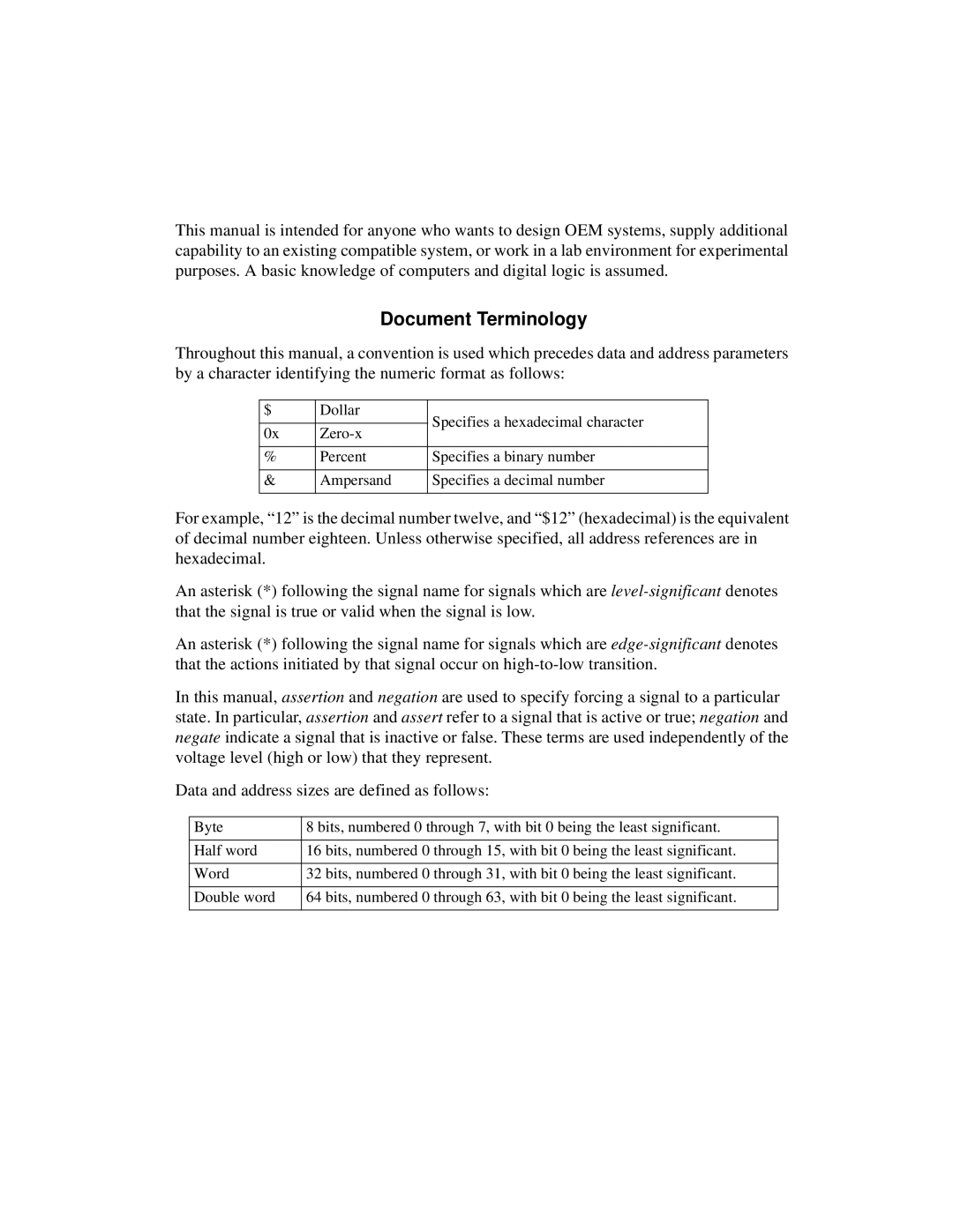
Throughout this manual, a convention is used which precedes data and address parameters by a character identifying the numeric format as follows:
$ | Dollar | Specifies a hexadecimal character | |
|
| ||
0x | |||
| |||
|
|
| |
% | Percent | Specifies a binary number | |
|
|
| |
& | Ampersand | Specifies a decimal number | |
|
|
|
For example, “12” is the decimal number twelve, and “$12” (hexadecimal) is the equivalent of decimal number eighteen. Unless otherwise specified, all address references are in hexadecimal.
An asterisk (*) following the signal name for signals which are
An asterisk (*) following the signal name for signals which are
In this manual, assertion and negation are used to specify forcing a signal to a particular state. In particular, assertion and assert refer to a signal that is active or true; negation and negate indicate a signal that is inactive or false. These terms are used independently of the voltage level (high or low) that they represent.
Data and address sizes are defined as follows:
Byte | 8 bits, numbered 0 through 7, with bit 0 being the least significant. |
|
|
Half word | 16 bits, numbered 0 through 15, with bit 0 being the least significant. |
|
|
Word | 32 bits, numbered 0 through 31, with bit 0 being the least significant. |
|
|
Double word | 64 bits, numbered 0 through 63, with bit 0 being the least significant. |
|
|