Operating Instructions
2 |
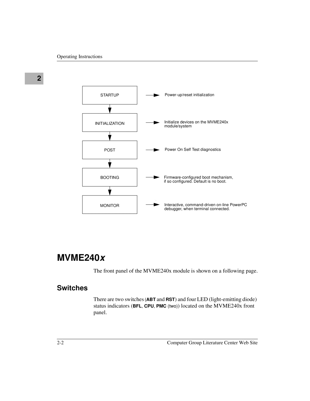
STARTUP
INITIALIZATION
Initialize devices on the MVME240x module/system
POST
Power On Self Test diagnostics
BOOTING
MONITOR
Interactive,
MVME240x
The front panel of the MVME240x module is shown on a following page.
Switches
There are two switches (ABT and RST) and four LED
Computer Group Literature Center Web Site |