Block Diagram
Clock Ratios and Operating Frequencies
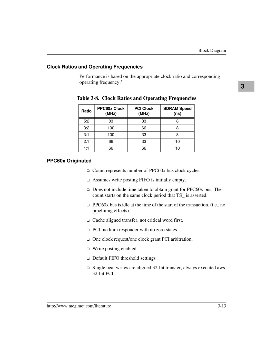
Performance is based on the appropriate clock ratio and corresponding operating frequency:’
3 |
Table 3-8. Clock Ratios and Operating Frequencies
Ratio | PPC60x Clock | PCI Clock | SDRAM Speed | |
(MHz) | (MHz) | (ns) | ||
| ||||
|
|
|
| |
|
|
|
| |
5:2 | 83 | 33 | 8 | |
|
|
|
| |
3:2 | 100 | 66 | 8 | |
|
|
|
| |
3:1 | 100 | 33 | 8 | |
|
|
|
| |
2:1 | 66 | 33 | 10 | |
|
|
|
| |
1:1 | 66 | 66 | 10 | |
|
|
|
|
PPC60x Originated
❏Count represents number of PPC60x bus clock cycles.
❏Assumes write posting FIFO is initially empty.
❏Does not include time taken to obtain grant for PPC60x bus. The count starts on the same clock period that TS_ is asserted.
❏PPC60x bus is idle at the time of the start of the transaction. (i.e., no pipelining effects).
❏Cache aligned transfer, not critical word first.
❏PCI medium responder with no zero states.
❏One clock request/one clock grant PCI arbitration.
❏Write posting enabled.
❏Default FIFO threshold settings
❏Single beat writes are aligned
http://www.mcg.mot.com/literature |
