AT Commands For Cdma Wireless Modems Reference Guide
Revision Level Date Description
AT Commands for Cdma Wireless Modems
Multi-Tech logo is a trademark of Multi-Tech Systems, Inc
Country By Email By Phone
Contents
Call Control Commands
Supplementary Services Commands
Position Determination GPS AT Commands
Provisioning AT Commands 124
Reference Information 166
AT Command Examples 171
Table of Contents
Related References
Scope of This Document
Definitions
Format message is supported
Power from the base stations the mobile sees
Cdma revision of the mobile or base station
PRL is loaded into the phone and is saved in NV-RAM
Command Line
Line Settings
Information Responses and Result Codes
Cell Broadcast Message Stored in Memory +CBMI
Cell Broadcast Message Directly Displayed +CBM
Cell Environment Description Indication +CCED
SMS Status Report Indication Directly Displayed +CDS
Call Waiting Indication +CCWA
SMS Status Report Indication Stored in Memory +CDSI
Values Callerid
Caller ID Presentation +CLIP
Key Press or Release +CKEV
Incoming Message Directly Displayed +CMT
Type
Incoming Message Stored in Memory +CMTI
Mode Preference +COPS
Registration & Roaming +CREG
Values stat
RxLev Indication +CSQ
Incoming Call +CRING
Incoming Call +RING
Call Connected +WCNT
Call Answered +WANS
Call Ended +WEND
Values Call type
Flash Indication +WFSH
Feature Notification Message +WFNM
Response syntax +WEND reason
ATH
General Indicator +WIND
Call Originated +WORG
Command syntax AT+WIND=IndLevel
Call Privacy Indication +WPRV
Prv
Roaming Indication +WROM
Emergency Mode +WSOS
Roam
Flag
Current NAM Change +WNAM
Voice Mail Indicator +WVMI
SMS Message Storage Full +WMGF
Leaving power save Entering power save
Power Save +WSPS
Response Syntax +WSPS state
State
Electronic Serial Number +CGSN
Request Revision Identification +CGMR
Select TE Character Set +CSCS
Values Character Set
Request Imsi +CIMI
Repeat Last Command a
Capabilities List +GCAP
Phone Offline +CPOF
Set Phone Functionality +CFUN
Command syntax AT+CFUN=functionality level
Values Functionality level
AT+CFUN?
Command syntax AT+CMEE=error reporting flag
Report Mobile Equipment Errors +CMEE
Phone Activity Status +CPAS
Keypad Control +CKPD
Command syntax AT+CRMP=call type,volume,type,index
Command syntax AT+CCLK=date and time string
Clock Management +CCLK
Ring Melody Playback +CRMP
Subscriber Number +CNUM
Ringer Sound Level +CRSL
Select Type of Address +CSTA
Values Sound level
Command syntax AT+WMSN
View Modem Timers +WTMR
Modem Serial Number +WMSN
AT+WTMR
Command syntax ATDnb
Dial Command D
Direct Dial Syntax
Command syntax ATDindex ATDmemname ATDmemindex
Hang-Up Command H
Command syntax ATH
Phonebook Syntax
Command syntax ATA
Extended Error Report +CEER
Command syntax AT+CEER
Answer a Call a
Dtmf Start and Stop Continuous +WSDT, +WSDS
Dtmf Signals +VTD, +VTS
Automatic Dialing with DTR %Dn
Redial Last Telephone Number DL
Automatic Answer S0
Command syntax AT+CICB=mode
Values Mode
Command syntax AT+CSNS
Incoming Call Bearer +CICB
Microphone Gain +VGT
Volume Gain Control +VGR
Speaker & Microphone Selection +SPEAKER
Microphone Mute Control +CMUT
Values ActiveSpkMic
Side Tone Modification +SIDET
Echo Cancellation +ECHO
Values Val1
Val2
Initialize Voice Parameters +VIP
TTY Mode +WTTY
AT+VIP
AT+WTTY
Valid value ranges Represents an unknown signal quality
Signal Quality +CSQ
Automatic Cdma Only Cdma or Amps only Analog only
AT+CSQ
Band
Band Preference +WBND
Command syntax AT+WRMP=mode
Home Networks only, as defined in the PRL default value
Roam Preference +WRMP
Roaming on Affiliated networks, as defined in the PRL
Stat
Network Registration & Roaming +CREG
Read Current NAM +WCNM
Change NAM Selection +WNAM
Values Nam
AT+WSOS=1 Error
Command syntax AT+WSOS=flag
AT+WSOS?
AT+WSOS=?
Enable output of ERI indicators 64 through
Suppress output of ERI indicators 64 through
Command syntax AT+WRMW=value
Extended Roam Indication +WRMW
Enter PIN +CPIN
SIM Card Operational Commands
Enter PIN2 +CPIN2
Command syntax AT+CPINC Response syntax +CPINC n1,n2,k1,k2
PIN Remaining Attempt Number +CPINC
Passwd
Facility Lock +CLCK
AT+CLCK?
AT+CLCK=AO,2
Card Identification +CCID
Change Password +CPWD
Oldpwd
Newpwd
Parameters Definition
New Message Acknowledgement +CNMA
Select Message Service +CSMS
Preferred Message Storage +CPMS
Show Text Mode Parameters +CSDH
Bfr
New Message Indication +CNMI
Oa/da
Read Message +CMGR
AT+CMGR=1
AT+CMGR=2 +CMS Error AT+CPMS=SR+CNMI=,,,2
AT+CMSS=3
Index Place of storage in memory
List Message +CMGL
Encoding Length Length of the text message in bytes
Da Destination address value in string format
Send Message +CMGS
Cbn Call Back Number
Send Message From Storage +CMSS
Write Message to Memory +CMGW
Delete Message +CMGD
Command syntax AT+CMGD=Index ,DelFlag
Values index
DelFlag
Select Broadcast Messages +CSCB
Command syntax AT+CSCB=mode
Message Status Modification +WMSC
Message
Change SMS Status +WUSS
Message Overwriting +WMGO
Set Timestamp of MT SMS +WSTM
Set SMS Compose Language and Encoding +WSCL
Values Lang
Enc
Command syntax AT+CCFC= number
Command e.g. ATD*72 Forwarded
Call Forwarding +CCFC
Number The phone number to forward all calls to
Calling Line Identification Presentation +CLIP
Calling Line Identification Restriction +CLIR
AT+WFSH
Send Flash to Base Station +WFSH
List Current Call State +CLCC
Select Mode +FCLASS
Using AT Commands During a Data Connection
Switch From Online to Offline Mode
Switch From Offline to Online Mode
Disables reporting of local port rate
Command syntax AT+CRC
Command syntax AT+ILRR=value
Cellular Result Codes +CRC
V42 Bis Data Compression +DS
Command syntax AT+DS=dir,neg,P1,P2
AT+DS?
Disable reporting Enable reporting
This syntax is for setting the +DR reporting method
Command syntax AT+DR=val
V42 Bis Data Compression Report +DR
Fixed DTE Rate +IPR
Command syntax AT+ICF= format, parity
DTE-DCE Character Framing +ICF
Values Format
DTE-DCE Local Flow Control +IFC
Set DCD Signal &C
Set DSR Signal &S
Set DTR Signal &D
Back to Online Mode O
Result Code Suppression Q
Auto-Tests &T
DCE Response Format
Echo E
Values Num
Command syntax AT&V
Display Configuration &V
AT&V
Save Configuration &W
Restore Factory Setting &F
Command syntax ATInum
Request Identification Information
Select Phonebook Memory Storage +CPBS
Command syntax AT+CPBS=bk
AT+CPBS=?
AT+CPBS=EN AT+CPBS?
Command syntax AT+CPBF=string
Command syntax AT+CPBU?
Return Selected Phonebook Locations +CPBU
Find Phonebook Entries +CPBF
String
Write Phonebook Entry +CPBW
+CME Erro
AT+CPIN2? Ruim PIN2
Command syntax AT+CPBP= phone number
Command syntax AT+CPBR=first,last
Phonebook Read +CPBR
Phonebook Search +CPBP
Delete Calls From Phonebook +WDCP
Avoid Phonebook Init +WAIP
Values Call phonebook
Command syntax AT+WPDST=type
This command sets and returns the PD session type
Position Determination Session Type +WPDST
Session to provide the last position info available
Position Determination Data Download +WPDDD
Position Determination Operating Mode +WPDOM
Duration
Position Determination NV Privacy Level +WPPRV
Position Determination Privacy Level +WPDPL
Time
Values Level
Values Setting
Position Determination Transport Setting +WPTLM
Command syntax AT+WPTLM=setting
DBM Data Burse Message
Position Determination Start Session +WPDSS
Values Service
Position Determination End Session +WPDES
Performance
AT+WPDSS=P
Position Determination Start Session Result +WPDSS
AT+WPDSS=PV
Set Port of gpsOne Session +WPDPT
Set IP Address of gpsOne Session +WPDIP
Values Ipaddress
Values Port
Request Model Identification +WGMM
Manufacturer Identification +WGMI
Cell Environment and RxLev Indication +CCED
Requested dump
Command syntax AT+CCED=mode, requested dump
Mobile Equipment Event Reporting +CMER
Analog Digital Converters Measurements +ADC
Write Gpio Value +WIOW
Read Gpio Value +WIOR
Gpio to read
Value
AT+WTONE?
Play Tone +WTONE
AT+WTONE=0 AT+WTONE=?
Hardware Version +WHWV
Play Dtmf Tone +WDTMF
Mode=1
Status Request +WSTR
Select Voice Gain +WSVG
Values Path
32kHz Sleep Mode +W32K
Ring Indicator Mode +WRIM
Default
Change Default Melody +WCDM
Software Version +WSSW
Values Melody
Custom Character Set +WCCS
Command syntax AT+WCCS=mode,table,char 1,char
Change Default Player +WCDP
Cphs Command +CPHS
FctId
Status
Set Standard Tone +WSST
Reset +WRST
Command syntax AT+WPRV=voice privacy level
Normal default Private
Set Voice Privacy Level +WPRV
Values Voice privacy level
AT+CSQ? +CME Error
Command syntax AT+WPIN=mode,current val,new val
Security PIN +WPIN
Current val & new val
Minute Alert +WMBP
Request PRL Version Information +WPRL
Interval
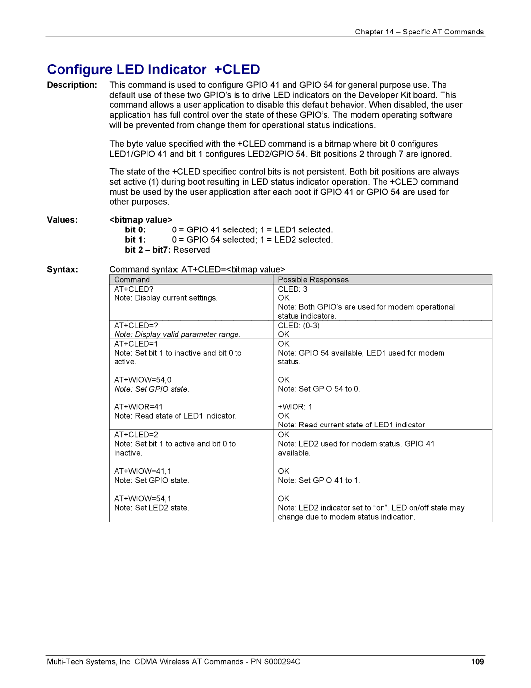
Values Bitmap value
Configure LED Indicator +CLED
Bit
Bit 2 bit7 Reserved Syntax
Keypad disabled Keypad enabled
Keypad Enable/Disable +WPAD
Command syntax AT+WPAD=mode
Summary
Overview of SIM Application ToolKit
Functionality
Profile Download
Data Download to SIM
Messages Exchanged During a SIM ToolKit Operation
Menu Selection
Call control by SIM
113
Timeout
Config
SIM ToolKit Set Facilities +STSF
Autoresponse
SIM ToolKit Indication +STIN
Error Codes
Unsolicited Result
Last SIM Toolkit Indication
AT+STIN? +CME Error
AT+STIN?
AT+STGI=0
SIM ToolKit Get Information +STGI
Command syntax +STGI=Cmd
+STGI=?
+STGI
Idx 1
Alpha Identifier menu
NbItems 1
Alpha Idx Label
CalledNb
DefaultItem 1
SubAdress
Class
Error Codes
Values when Cmd=11 Setup Event List
Unsolicited Result SIM ToolKit Control Response +STCR
Evt
Values CmdType
SIM ToolKit Give Response +STGR
Possible Error Codes
Values when CmdType=4 Setup call
Detected
Indication +STIN has not been received
+STGR=?
Command syntax +STGR=CmdType,Result,Data
Mobile Directory Number +WMDN
Service Programming Code +WSPC
Values Lock type
Code
SID and NID +WSID
Set Imsi +WIMI
SID number
NID number
Slot Cycle Index +WSCI
Access Overload Class +WAOC
Primary Browser Gateway +WBGP
Secondary Browser Gateway +WBGS
Primary Cdma Channels +WPCC
Packet Dial String +WPDS
Secondary Cdma Channels +WSCC
Values enable
Service Option Management +WSOM
Commit Changes +WCMT
Home page SO 0 IS96A
Read SID/NID Entries +WSNR
Command syntax AT+WSNR=index
Location in SID/NID list to read
Error AT+WPDS?
Service Programming Example
AT+WSCI=1 AT+WCMT=0
Reset to Default Configuration Z0
Remote Async/Fax Command
Select Tone Dialing T
Command syntax ATSn=value
Command syntax ATP
Select Pulse Dialing P
Basic S-Registers SX
Defaultlength
Error Control Operation +EB
Numeric Parameter Control +EFCS
Values Breakselection
Error Control Selection +ES
Error Control Report +ER
Values Origrqst
Origfbk
Error Control Selection +ETBM
Error Control Selection +ESR
Timer
Values PendingTD
Request Manufacture Identification +GMM
Request Manufacture Identification +GMI
Request Revision Identification +GMR
Request Global Object Identification +GOI
Request Product Serial Number Identification +GSN
Modulation Selection +MS
Modulation Reporting Control +MR
Modulation Automode Control +MA
Reporting Control +MV18R
Selection +MV18S
Fbktimeenable
Cellular Extension +CXT
Dfltansmode
Query Service +CAD
Configuration String +CFG
Um Interface Data Compression Reporting +CDR
Command syntax AT+CRM=Val
Command syntax AT+CDS=Val
Um Interface Data Compression +CDS
Set Rm Interface Protocol +CRM
Command State Inactivity Timer +CQD
Battery Charge +CBC
Command syntax AT+CQD=val
Command syntax AT+CMIP
AT+CBIP? Error
Command syntax AT+CBIP
Base Station IP Address +CBIP
AT+CBIP?
Values Class
Serving System +CSS
PA PF PCS
Command syntax AT+CFC=Val
Command syntax AT+CMUX=n
Select Multiplex Option +CMUX
Um Interface Fax Compression +CFC
IWF Content List +CGCAP
Dial Command for Voice Calls +CDV
Hang-up Voice +CHV
Command syntax AT+CGOI
Um Packet Data Inactivity Timer +CTA
Command syntax AT+CTA=val
IWF Device Identification +CGOI
IS-707.3 Fax Parameters
IS-707.3 Fax Action Commands
Command syntax AT$QCDMG
Transition to Diagnostics Monitor $QCDMG
Command syntax AT$QCQNC=Val
Quick Net Connect $QCQNC
Originate M-to-M Packet Data Call $QCMTOM
Protocol Revision in Use $QCPREV
Dump RLP Protocol Statistics $QCRLPD
Values Number
Reset PPP Protocol Statistics $QCPPPR
Reset RLP Protocol Statistics $QCRLPR
Dump PPP Protocol Statistics $QCPPPD
Dump IP Protocol Statistics $QCIPD
Reset UDP Protocol Statistics $QCUDPR
Reset IP Protocol Statistics $QCIPR
Dump UDP Protocol Statistics $QCUDPD
Dump TCP Protocol Statistics $QCTCPD
Set Data Service Option $QCSO
Reset TCP Protocol Statistics $QCTCPR
Clear Mobile Error Log $QCCLR
Answer Incoming Voice Call $QCCAV
Pre-arrangement Setting $QCVAD
Automatic Packet Detection $QCPKND
Command syntax AT$QCRL3D
Command syntax AT$QCMDR=Val
Set DM Baud Rate $QCDMR
Set Medium Data Rate $QCMDR
SCRM’ing Selection $QCSCRM
Reset RLP 3 Protocol Statistics $QCRL3R
SCH Selection $QCTRTL
SCH Selection $QCMIP
Command syntax AT$QCMIP=Val
AT$QCMIP? AT$QCMIP=?
AT$QCMIP=0
RFC2002bis Selection $QCMIPT
MIP Selection $QCMIPP
Current Active Profile $QCMIPEP
String The network access identifier text to be stored
Command syntax AT$QCMIPGETP=Val
Command syntax AT$QCMIPNAI=String,Val
Return Profile Information $QCMIPGETP
Set MN-AAA Shared Secrets $QCMIPMASS
Set Reverse Tunneling $QCMIPRT
Set MN-AAA Shared Secrets $QCMIPMASSX
Set MN-HA Shared Secrets $QCMIPMHSS
Command syntax AT$QCMIPMASPI =SPI,Val
Command syntax AT$QCMIPMHSSX =HEX,Val
Set MN-HA Shared Secrets $QCMIPMHSSX
Set MN-AAA Shared Secrets $QCMIPMASPI
Command syntax AT$QCMIPPHA =IP,Val
Command syntax AT$QCMIPMHSPI =SPI,Val
Set MN-HA Shared Secrets $QCMIPMHSPI
Set Primary HA IP Address $QCMIPPHA
Command syntax AT$QCMIPHA =IP,Val
Command syntax AT$QCMIPSHA =IP,Val
Set Secondary HA IP Address $QCMIPSHA
Set Home HA IP Address $QCMIPHA
MS Error Result Code +CME Error error
Specific Error Result Codes
Message Service Failure Result Code +CMS Error error
Extended Error Report +CEER Call Processing Codes
Final Result Codes
Parameters Storage
Intermediate Result Codes
Code Meaning
Codes for SMS-STATUS-REPORT +CDS and +CMGR
AT Commands for Amps Operation
AT Commands Supported When SIM Card Removed
Examples Where a Voice Call is Originated
Example 1 When the MS Has Already Been Powered On
Example When the MS is powered on
Example with Incoming Calls
Examples About Short Messages
Example of a Call Waiting Situation
Example 1 Receive a Short Message
Example 2 Send a Short Message
AT+WSCL=6,4
Example 3 Read Short Messages
Status report
Ind Message type indicator
MO delivery acknowledge message
Mr Message Reference
Roaming Indication +WROM Chapter
Incoming Message Directly Displayed +CMT Chapter
Enhanced Roaming Indication +WERI
AT+WSOS +WSOS0 AT+COPS=0,0
Emergency Mode +WSOS Chapter
Only if the message privacy value is 0 Normal
Read message +CMGR Chapter
179
List Message +CMGL Chapter
Command syntax AT+CMGL=stat
Response syntax +CMGL index,stat,da/oa,lang
Encod,lengthCRLFdata for SMS-DELIVER and SMS-SUBMIT, may be
Reply Message reply option
Send Message +CMGS Chapter
No Acknowledge
Cbn CR entered text ctrl-Z / ESC
Write Message to Memory +CMGW Chapter
Verizon. System Selection +WVSS
Service Programming Code +WSPC Chapter
Syntax +WVSS pref
Programming In Progress +WOT1
Initial Programming Required +WOT0
Programming Successful +WOT2
Programming Unsuccessful +WOT3
NAM Download Ok +WOTN
SPL Unlocked +WOTS
MDM Download Ok +WOTM
MSI Download Ok +WOTI
Excess SPC Failures +WLCK
Command syntax AT+WPLCK=level
Position Determination Lock Level +WPLCK
AT+WPLCK=?
Response Syntax
+CDS ind, mr, ra, tora, scts, dt, st Text mode
AT+CSQ
Use any four digit value. e.g
Allow data calls Barr data calls Query status
Syntax for Facility Lock
AT+CLCK=AO,9
190
Channel
No service 800 MHz 1900 MHz
Packet Zone Identifier +PZID
Boot URL +WBURL
Trusted Domain +WTDMN
Wiota Connection Control +WIOTA
Proxy Address +WDPXY
Sprint. System Selection +WSSS
Preparing Data Services +WOAP
Iota Error +WOAE
Command syntax +WSUM?
Please Retry +WOAR
Command syntax +WRMM
Reset MIN and MDN to factory defaults +WRMM
AT+WRMM