1.4 LED indicators information
There are many LEDs on the front panel of switch. After the initial power on, these LEDs will reflect the current status within the switch as explained below:
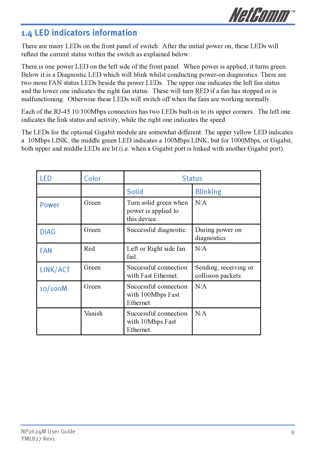
There is one power LED on the left side of the front panel. When power is applied, it turns green. Below it is a Diagnostic LED which will blink whilst conducting
Each of the
The LEDs for the optional Gigabit module are somewhat different. The upper yellow LED indicates
a10Mbps LINK, the middle green LED indicates a 100Mbps LINK, but for 1000Mbps, or Gigabit, both upper and middle LEDs are lit (i.e. when a Gigabit port is linked with another Gigabit port).
LED | Color | Status | |
|
|
|
|
|
| Solid | Blinking |
|
|
|
|
Power | Green | Turn solid green when | N/A |
|
| power is applied to |
|
|
| this device. |
|
DIAG | Green | Successful diagnostic. | During power on |
|
|
| diagnostics |
FAN | Red | Left or Right side fan | N/A |
|
| fail. |
|
LINK/ACT | Green | Successful connection | Sending, receiving or |
|
| with Fast Ethernet. | collision packets |
10/100M | Green | Successful connection | N/A |
|
| with 100Mbps Fast |
|
|
| Ethernet. |
|
| Vanish | Successful connection | N/A |
|
| with 10Mbps Fast |
|
|
| Ethernet. |
|
NP2624M User Guide | 9 |
YML827 Rev1 |
|