Fast EtherHub 3500 System User’s Guide
There are 5 LEDs representing the percentage of network bandwidth in use by the attached (or isolated) segment. When active, these LEDs look like a stereo’s equalizer display. The hub updates this display every 0.5 seconds.
For example, if network utilization reaches 1%, the LED labeled 1 will light. However, if network utilization rises above 1% (e.g., 30%), the LED labeled 30 and all the other LEDs before it (i.e., 1, 5, and 15) will light in rapid succession.
These LEDs monitor the share of valid network frames transmitted by this hub within a 100 Mbps bandwidth. They provide a quick way to monitor the current traffic load relative to the capacity available to the attached/isolated segment.
Collision Indicators
Color: | Green and yellow |
Label: | Collision |
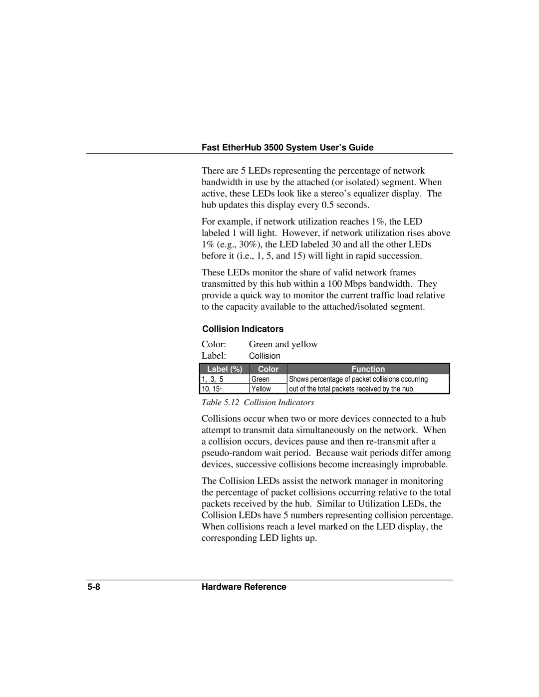
Label (%)
1, 3, 5
10, 15+
Color
Green
Yellow
Function
Shows percentage of packet collisions occurring out of the total packets received by the hub.
Table 5.12 Collision Indicators
Collisions occur when two or more devices connected to a hub attempt to transmit data simultaneously on the network. When a collision occurs, devices pause and then
The Collision LEDs assist the network manager in monitoring the percentage of packet collisions occurring relative to the total packets received by the hub. Similar to Utilization LEDs, the Collision LEDs have 5 numbers representing collision percentage. When collisions reach a level marked on the LED display, the corresponding LED lights up.
Hardware Reference |