Fast EtherHub 3500 System User’s Guide
2-8 Installing the System
connect one end of the cable to the MDI port on the extender
module, and the other end to the MDI-X port on the target
device (or vice versa). When inserting an RJ-45 plug, be sure
the tab on the plug clicks into position to ensure that it is
properly seated. Note that as a general rule, the length of any
twisted-pair cable should not exceed 100 meters.
Connecting Fiber Optic Cabling - For the 100BASE-FX module,
prepare fiber optic cable with SC or ST connectors at both
ends. When connecting the module directly to an end-node
device (e.g., workstation or file server), run cable from the Rx
(Tx) port on the module to the Tx (Rx) port on the target
device. Also, when daisy-chaining SmartExtender Modules,
make similar connections between the current module and the
next device in the stack. When inserting a cable, be sure the tab
on the plug clicks into position, to ensure that it is properly
seated. Note that as a general rule, the length of fiber optic
cable should not exceed 2 kilometers. However, power
budgeting must be considered when calculating the maximum
cable length for your specific environment (as described later in
this chapter).
Distance Limit and Power Loss in Fiber Optics - When using fiber
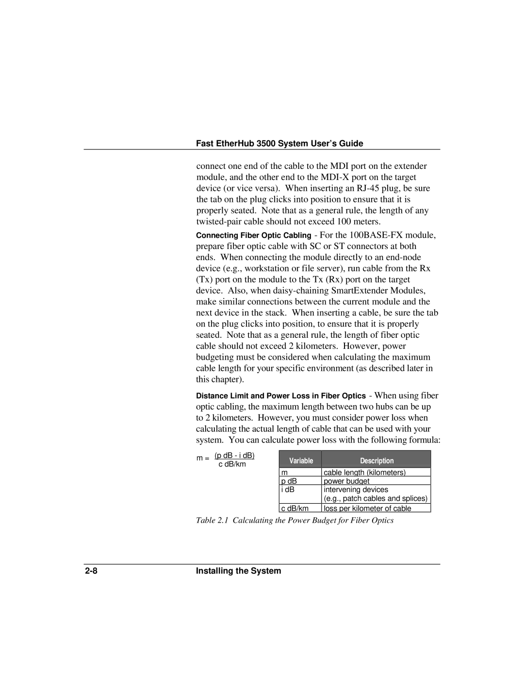
optic cabling, the maximum length between two hubs can be up
to 2 kilometers. However, you must consider power loss when
calculating the actual length of cable that can be used with your
system. You can calculate power loss with the following formula:
m = (p dB - i dB)
c dB/km Variable Description
m
cable length (kilometers)
p dB power bud
g
et
i dB intervening devices
(e.g., patch cables and splices)
c dB/km
loss per kilometer of cable
Table 2.1 Calculating the Power Budget for Fiber Optics