BCM50 Installation and Maintenance Guide
Copyright Nortel Networks Limited
N0027152
BCM50 Installation and Maintenance Guide
Software License
Nortel Networks
Installing the main unit
Task List
Using Element Manager to set the basic parameters
Task List
Replacing a power supply
Task List N0027152
Contents
Contents
Chapter Viewing the BCM50 system LEDs
Chapter Installing the main unit
Chapter Configuring the BCM50 system
Chapter Connecting the BCM50 system to the LAN and WAN
194
Index
Contents N0027152
Regulatory information
North American regulatory information
Canadian Notice
Federal Communications Commission FCC Notice
Ringer Equivalence Number REN
EMI/EMC FCC Part
Regulatory information
Important safety instructions
Installation
Safety
Use of a music source
Enhanced 911 configuration
Radio-frequency interference
Telecommunication registration
International regulatory information
Additional safety information
ITU standardization compliance
Chapter
Getting started with BCM50
About this guide
Purpose
About BCM50
Organization
BCM50 key elements
BCM50 includes the following key elements
BCM50 features
Symbols and conventions used in this guide
Example Use the info command
Whichever set you are using
Related publications
Indicates book titles
CallPilot and Call Center Guides
How to get help
If you do not see an appropriate number in this list, go to
800-4NORTEL Use Express Routing Code ERC 1063#
European Free phone 00800 800
44-191-555-7980
Emeahelp@nortel.com
Mail
Getting started with BCM50 N0027152
Introducing the BCM50 hardware
Main units
BCM50 main unit ports and connectors
Introducing the BCM50 hardware
Port/connector Description
Expansion unit ports/connectors and descriptions
Expansion unit and media bay modules
Media bay modules
Expansion unit Main unit
Trunk MBMs
Module type What it does Special notes
Digital trunk media bay module
Brim faceplate
Station MBMs Sheet 1
Introducing the BCM50 hardware Station MBMs Sheet 2
DSM
Analog station media bay modules
ATA2 ASM8 ASM8+ Gasm Gasi
BCM50 hardware
Rackmount shelf
Patch panel
Wallmount bracket
Wiring field card WFC
Wallmount bracket
Power supply
Power supply adapter cord international users
BCM50 components
Uninterruptable power supply
Hard disk
Cooling fan
Cooling fan
RJ-21 telephony connector
Analog telephones
Field-replaceable units
Router card
Field-replaceable units
Telephones and adapters
Introducing the BCM50 hardware Media bay modules
Introducing the BCM50 hardware
ABC
Accessories
Introducing the BCM50 hardware N0027152
Viewing the BCM50 system LEDs
System status LEDs
Viewing the BCM50 system LEDs
System status LEDs during startup or reboot
Power Status Description
LAN port LEDs
System status LEDs states and descriptions
LAN port LED locations
Status Description
Adsl router LEDs BCM50a only
Describes the possible Adsl router LED states
Adsl router LED descriptions
LAN port LED indicators
Ethernet router LEDs BCM50e only
Describes the possible Ethernet router LED states
Media bay module LEDs expansion units only
Describes the possible MBM LED states
Following MBMs have additional LEDs
MBM LED descriptions
DTM LEDs
Describes the functions of the DTM LEDs
DTM LED functions
Status Descriptions
Brim LEDs
Describes the functions of the Brim LEDs
Brim LED functions
Determining Dhcp server configuration and IP address
Determining Dhcp server configuration and IP address
BCM50 main unit no integrated router
If an external Dhcp server is not present
BCM50a or BCM50e with integrated router
If an external Dhcp server is present
To disable the Dhcp server on the main unit
Page
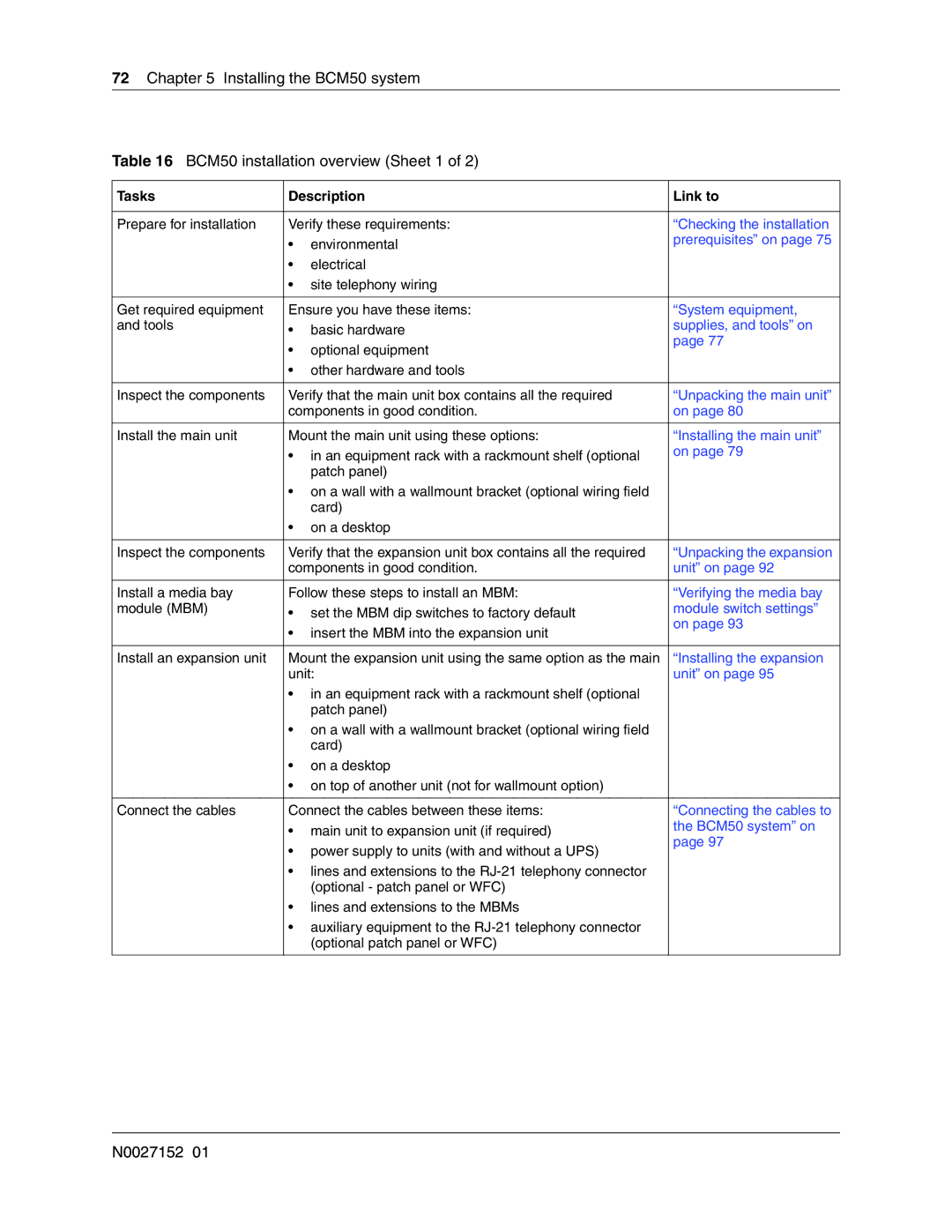
Installing the BCM50 system
Installing the BCM50 system
Tasks Description Link to
Supplies, and tools on
Installing telephones
Installing the BCM50 system N0027152
Checking the installation prerequisites
Checking the installation prerequisites
Environmental requirements
Electrical requirements
Site telephony wiring requirements
Digital loop
System equipment, supplies, and tools
Analog loop
Basic hardware
Optional equipment
Other hardware and tools
Installing the main unit
Shows the steps required to install the main unit
Installing the BCM50 unit in an equipment rack
Installing the main unit
Unpacking the main unit
To install the rackmount shelf in an equipment rack
Installing the BCM50 unit on the rackmount shelf
To install the BCM50 unit on the rackmount shelf
Attach the units to the rackmount shelf N0027152
To install a BCM50 unit on top of another unit
To install the power supply on the rackmount shelf
To install the patch panel optional
Installing the BCM50 unit on the wall
To install the BCM50 wallmount bracket
Wallmount bracket
To install the BCM50 unit on the wallmount bracket
Wallmount lock in unlock position
Attach the BCM50 unit to the wallmount bracket
Installing the wiring field card optional
To install the WFC
Repeat for each BCM50 power supply
Installing the BCM50 unit on a desktop or shelf
To install the BCM50 unit on a desktop or shelf
Next step
Installing an expansion unit
Installing an expansion unit
Unpacking the expansion unit
Verifying the media bay module switch settings
To set Gasm dip switches
To set Gatm dip switches
Gasm dip switch settings switch
Installing a media bay module in an expansion unit
Installing the expansion unit
To install a media bay module MBM
Installing an expansion unit N0027152
Connecting the cables to the BCM50 system
Connecting the cables to the BCM50 system
Connecting the expansion unit
Expansion unit
Connecting the expansion unit to the BCM50 Main Unit
To connect an expansion unit
Connecting the power supply
Default line and extension numbers
Default Extension numbers Line numbers
Expansion port
To connect a power supply using a UPS
To connect a power supply without a UPS
Connecting the lines and extensions
Wiring warnings
Read the warnings in Wiring warnings on
To connect the lines and extensions
Connecting telephone lines to the expansion units
To connect telephone lines to DTM, BRIM, or 4x16 MBMs
Connecting extensions to the expansion units
To connect analog telephone lines to the GATM4 or GATM8
To connect extensions to DSM16, DSM32, ASM8, or 4x16 MBMs
Connecting the auxiliary equipment
Connecting an auxiliary ringer
To install an auxiliary ringer
Connecting an external paging system
To install an external paging system
Connecting an external music source
Tip Paging tips
To connect the music source using the music source jack
Music source jack
To connect the cables to the wiring field card optional
To connect the cables to the patch panel optional
Next step
Installing telephones and peripherals
System telephones
Analog terminal adapter
Installing an emergency telephone
To install the emergency telephone
Installing telephones and peripherals
Central Answering Position CAP/eCAP
Installing IP Phones
Installing T7406 cordless systems
Installing telephones and peripherals N0027152
Installing the analog terminal adapter
Configuration overview
Refer to on page 45 for ATA2 specifications
Analog telephone
Installing the ATA2
Connecting the ATA2
This section provides information on installing the ATA2
Installing the analog terminal adapter
Chapter Installing the analog terminal adapter
To connect the ATA2
Mounting the ATA2
To mount the ATA2 on a wall
Test insertion loss measurement
ATA2 back view Mounting keyhole slots
Configuring the ATA2
Installing the analog terminal adapter N0027152
Configuring the BCM50 system
Configuring the BCM50 system
Initial parameters overview
Initial parameters
Startup parameters overview
Startup parameters
Configuring the BCM50 system N0027152
Using Telset Administration to set the basic parameters
Using Telset Administration to set the basic parameters
Configuring the initial parameters
To configure the IP address
To enter the keycodes
To configure the modem
To select the region
To select the telephony startup template and startDN
To initialize voice mail
To create Telset user accounts
Next step
Page
Using Element Manager to set the basic parameters
Using Element Manager to set the basic parameters
Accessing the BCM50 system
To download and install Element Manager
To connect to the BCM50 system
To configure the IP subsystem
Modify IP Settings attributes
Attribute Description
To configure the start-up template for telephony services
Cold Reset Telephony attributes
Attribute
Configuring the startup parameters
Click Install
Quick Install Wizard attributes
To enter a name for your system
To configure the date and time settings
To configure Dhcp server settings
Date and Time attributes
To configure IP Phones
Configure the Dhcp server attributes see Table
Dhcp server general settings attributes
IP Terminal Global Settings attributes
To configure Snmp settings
To configure Snmp community strings
Modify Snmp Settings attributes
Click Add.... The Add Community String dialog box opens
To configure the Snmp manager list
Configure the Add Community String attributes. see Table
To create user accounts
Click Ok Repeat steps 4 to 6 to add more community strings
Click Ok Repeat steps 4 to 6 to create more user accounts
Using the Startup Profile to configure parameters
Using the Startup Profile to configure parameters
Startup Profile requirements
Configuring basic parameters
To download the Startup Profile template
To customize a Startup Profile for your system
To load the Startup Profile data onto the BCM50 system
Next step
Using the Startup Profile to configure parameters N0027152
Completing the initial installation optional
Completing the initial installation optional
Configuring the media bay module
To configure the MBMs
Configuring modem settings
Checking for software updates
Configuring voice mail
Performing a backup
Customizing security policies
Connecting the BCM50 system to the LAN and WAN
Connecting the BCM50 system to the LAN and WAN
Connecting the BCM50 system to the LAN
Describes the function and use of each of the ports
LAN ports on the main unit Sheet 1
Port name Function
To connect the BCM50 system to the LAN
LAN ports on the main unit Sheet 2
Connecting the BCM50 system to the WAN
To connect the BCM50e main unit to the WAN
BCM50a main unit
BCM50e main unit
To connect the BCM50a main unit to the WAN
Proceed to Next step
Connecting the BCM50 system to the LAN and WAN N0027152
Testing basic BCM50 functionality
Testing basic BCM50 functionality
To test the main unit
To test the main unit without a valid keycode
To troubleshoot the main unit
To test the expansion unit
To troubleshoot the expansion unit
To test the MBM
To test a station MBM
To determine why an MBM does not appear in Element Manager
To determine why the ATA2 does not function
To test a trunk MBM
Reset to factory settings
To determine why there is no dial tone at the ATA2
To check the ATA2 wiring
Reset levels
Activate the reset feature
To perform a Level 1 and Level 2 reset
Set
Testing basic BCM50 functionality Level 1 reset
Level 2 reset
Replacing the BCM50 system components
Replacing the BCM50 system components
Replacing the BCM50 system components N0027152
Replacing a power supply
Replacing a power supply
Preparing the system for maintenance
Removing the power supply
To remove the power supply
Check for a recent backup of the BCM50 system programming
Connect the new power supply
To connect the new power supply
Returning the system to operation
Replacing a power supply N0027152
Replacing a main unit
Replacing a main unit
To disconnect the cables
Removing the main unit
To remove a rackmounted main unit
To remove a wallmounted main unit
Installing the new main unit
To remove a desktop mounted main unit
To connect the cables
To return the system to operation
Replacing a main unit N0027152
Refer to the following procedures to replace an MBM
Replacing a media bay module
Replacing a media bay module
To remove the MBM
Remove an MBM
To insert the new MBM
Replacing a media bay module N0027152
Replacing an expansion unit
Replacing an expansion unit
Disconnecting the cables
Removing the expansion unit
To disconnect the expansion unit cables
To remove a rackmounted expansion unit
To remove a wallmounted expansion unit
To remove a desktop-mounted expansion unit
Removing the MBM
Inserting the MBM in the new expansion unit
Installing the new expansion unit
Replacing an expansion unit
Replacing an internal component
Replacing an internal component
Special tools
Removing the main unit
Opening the main unit case
To remove a desktop-mounted main unit
To open the main unit case
Ensure that all the cables are removed from the main unit
BCM50 case screws
Use one of the following procedures to remove the component
Removing an internal component
Lift the top of the case off of the BCM50 unit
To remove the hard disk
Hard disk cables
To remove the fan
Hard disk and bracket screws
To remove the router card
Fan
Inserting the new component
To insert the new hard disk
Insert screws
Perform a restore or manual reprogram of the system
To insert the new fan
Closing the main unit case
To insert the new router card
To close the main unit case
Installing the main unit
Replacing the top of the case
To return the BCM50 system to operation
Replacing an internal component
RJ-21 telephony connector wiring chart
Appendix a RJ-21 telephony connector wiring chart
Appendix a
RJ-21 telephony connector wiring Sheet 2
LAN ports wiring chart
Appendix B LAN ports wiring chart
Appendix B
BCM50a BCM50e
Lists the wiring details for the LAN ports
LAN port wiring
Pin Signal
WAN ports wiring chart
On page 210 list the wiring details for the WAN ports
Appendix C WAN ports wiring chart
RJ-11 WAN port wiring
RJ-45 WAN port wiring
Expansion ports wiring chart
Lists the wiring details for the expansion ports
Appendix D Expansion ports wiring chart
Expansion port wiring Sheet 1
FS256 Receive Data + FS256 Receive Data
DTM wiring chart
Appendix E DTM wiring chart
Default line numbers on Line type Expansion port
Appendix E
Appendix E DTM wiring chart N0027152
Brim wiring chart
On page 216 list the wiring details for the RJ-45 ports
Appendix F Brim wiring chart
Brim RJ-45 port wiring
Appendix F Brim wiring chart Brim line numbering
Default line numbers on Port number Expansion port
Gatm wiring chart
Appendix G Gatm wiring chart
GATM4 RJ-21 connector wiring Sheet 1
Appendix G
GATM8 RJ-21 connector wiring Sheet 1
Ring Slate-Violet
Appendix G Gatm wiring chart N0027152
4x16 wiring charts
Appendix H 4x16 wiring charts
4x16 RJ-11 port wiring
Appendix H
Lists the wiring details for the RJ-21 connector on
Appendix H 4x16 wiring charts 4x16 default line numbering
4x16 RJ-21 connector wiring Sheet 1
Default line number on Port number Expansion port
Tip Black-Brown
Appendix H 4x16 wiring charts N0027152
DSM16 and DSM32 wiring charts
Appendix I DSM16 and DSM32 wiring charts
DSM16 and DSM32 RJ-21 connector wiring Sheet 1
Appendix
Set Pin Connection Wire color RJ-21
241
242
243
ASM8, ASM8+, and Gasm wiring chart
Lists the wiring details for the RJ-21 connector on the ASM
Appendix J ASM8, ASM8+, and Gasm wiring chart
ASM RJ-21 connector wiring Sheet 1
Default DN on Set Pin Connection
Expansion port No connection Violet-Slate Slate-Violet
Regional default system values
Appendix K
System region attributes
Regional language default values
Default languages by region
Appendix K System region attributes
South/Central America language support
Regional caller ID display formats
Regional companding law
Regional media bay module availability
Companding law by region
Regional PRI line protocol support
Shows the PRI line protocol support by region
PRI line protocol supported, by region Sheet 1
Isdn line services
Isdn line services
Mcdn over PRI SL-1
Protocol Region Available Isdn services
Define time zones by country and language
Time/date formats based on language
Language/Country Time/Date format
System defaults
Region defaults Sheet 1
Restriction filter defaults
Appendix K System region attributes Region defaults Sheet 2
Default dialing restrictions, by profile
Digital trunk types
Provides a description of the types of digital trunk types
Digital trunk types and descriptions Sheet 1
Digital trunk Description Types
CallPilot region default languages by country
Default voice mail
CallPilot regions
Analog trunk types
CallPilot feature default anomalies
Spain Sweden Switzerland
Appendix K System region attributes N0027152
Index
Numerics
Index
Dhcp
LED
PRI
CAP
Index N0027152