54Chapter 5 Configuring the R2MFC MBM
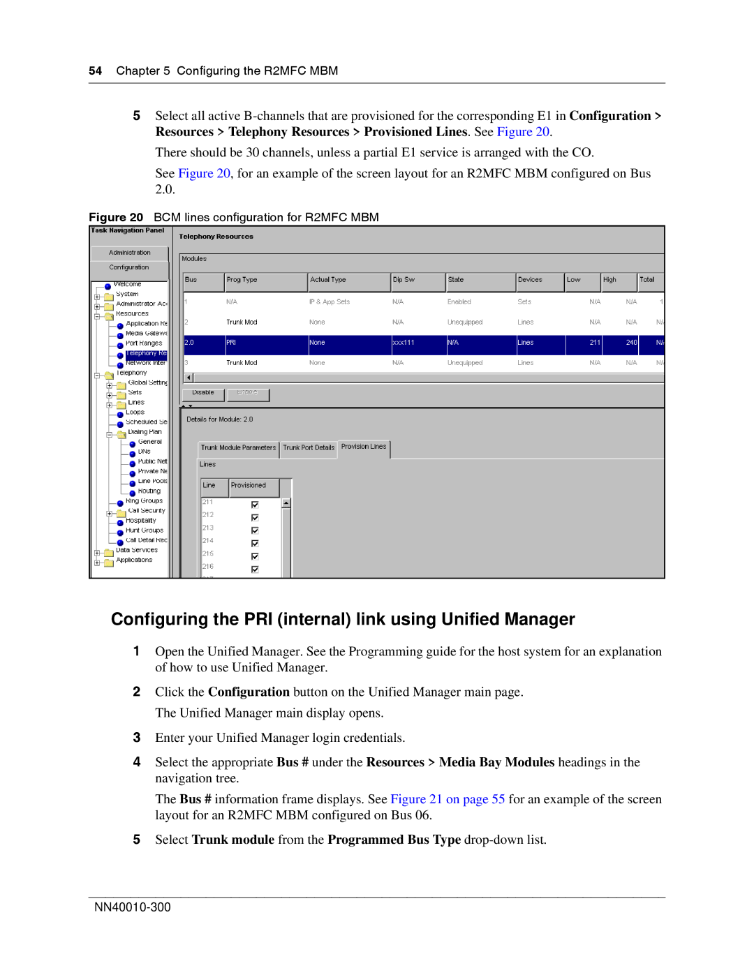
5Select all active
There should be 30 channels, unless a partial E1 service is arranged with the CO.
See Figure 20, for an example of the screen layout for an R2MFC MBM configured on Bus 2.0.
Figure 20 BCM lines configuration for R2MFC MBM
Configuring the PRI (internal) link using Unified Manager
1Open the Unified Manager. See the Programming guide for the host system for an explanation of how to use Unified Manager.
2Click the Configuration button on the Unified Manager main page. The Unified Manager main display opens.
3Enter your Unified Manager login credentials.
4Select the appropriate Bus # under the Resources > Media Bay Modules headings in the navigation tree.
The Bus # information frame displays. See Figure 21 on page 55 for an example of the screen layout for an R2MFC MBM configured on Bus 06.
5Select Trunk module from the Programmed Bus Type
