52 Chapter 5 Configuring the R2MFC MBM
Signaling
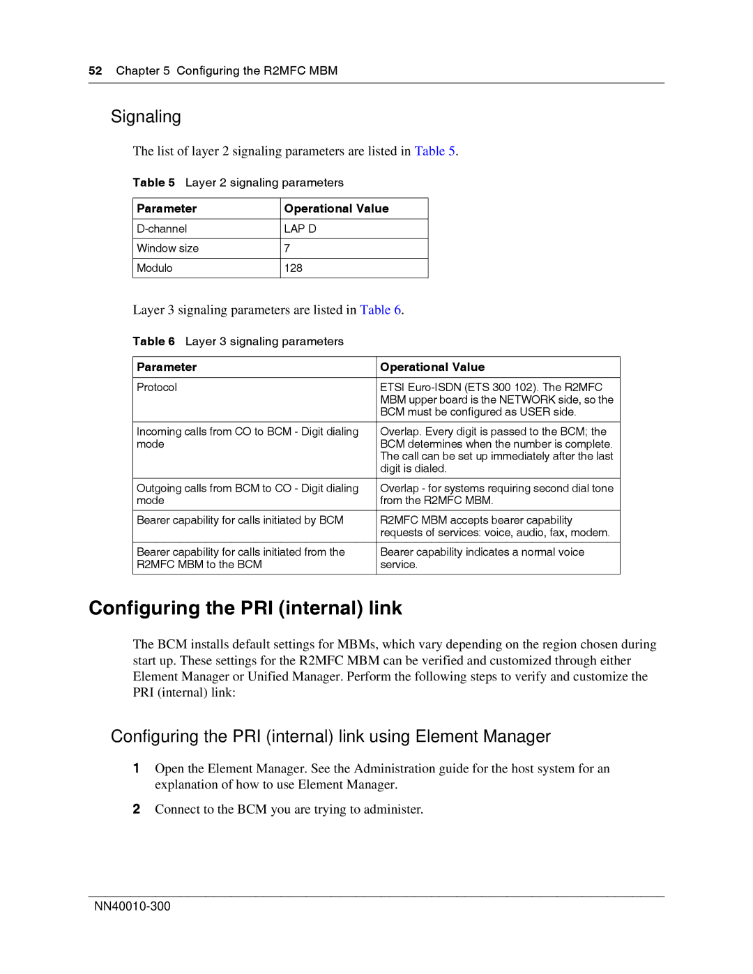
The list of layer 2 signaling parameters are listed in Table 5.
Table 5 Layer 2 signaling parameters
Parameter | Operational Value |
|
|
LAP D | |
|
|
Window size | 7 |
|
|
Modulo | 128 |
|
|
Layer 3 signaling parameters are listed in Table 6.
Table 6 Layer 3 signaling parameters
Parameter | Operational Value |
|
|
Protocol | ETSI |
| MBM upper board is the NETWORK side, so the |
| BCM must be configured as USER side. |
|
|
Incoming calls from CO to BCM - Digit dialing | Overlap. Every digit is passed to the BCM; the |
mode | BCM determines when the number is complete. |
| The call can be set up immediately after the last |
| digit is dialed. |
|
|
Outgoing calls from BCM to CO - Digit dialing | Overlap - for systems requiring second dial tone |
mode | from the R2MFC MBM. |
|
|
Bearer capability for calls initiated by BCM | R2MFC MBM accepts bearer capability |
| requests of services: voice, audio, fax, modem. |
|
|
Bearer capability for calls initiated from the | Bearer capability indicates a normal voice |
R2MFC MBM to the BCM | service. |
|
|
Configuring the PRI (internal) link
The BCM installs default settings for MBMs, which vary depending on the region chosen during start up. These settings for the R2MFC MBM can be verified and customized through either Element Manager or Unified Manager. Perform the following steps to verify and customize the PRI (internal) link:
Configuring the PRI (internal) link using Element Manager
1Open the Element Manager. See the Administration guide for the host system for an explanation of how to use Element Manager.
2Connect to the BCM you are trying to administer.
