Chapter 2 Overview 25
Power connectors
The R2MFC MBM receives its power from the BCM chassis through a power connector on the back of the module.
Figure 4 shows the placement of the power connectors.
Figure 4 R2MFC MBM back
DS256 and power connector
MBM DIP switches
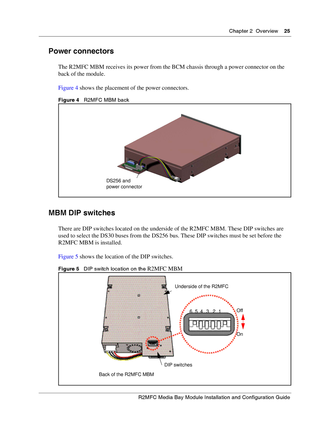
There are DIP switches located on the underside of the R2MFC MBM. These DIP switches are used to select the DS30 buses from the DS256 bus. These DIP switches must be set before the R2MFC MBM is installed.
Figure 5 shows the location of the DIP switches.
Figure 5 DIP switch location on the R2MFC MBM
Underside of the R2MFC
6 | 5 | 4 | 3 | 2 | 1 | Off |
On
![]() DIP switches
DIP switches
Back of the R2MFC MBM
