Configuring DIP switch settings and definitions 95
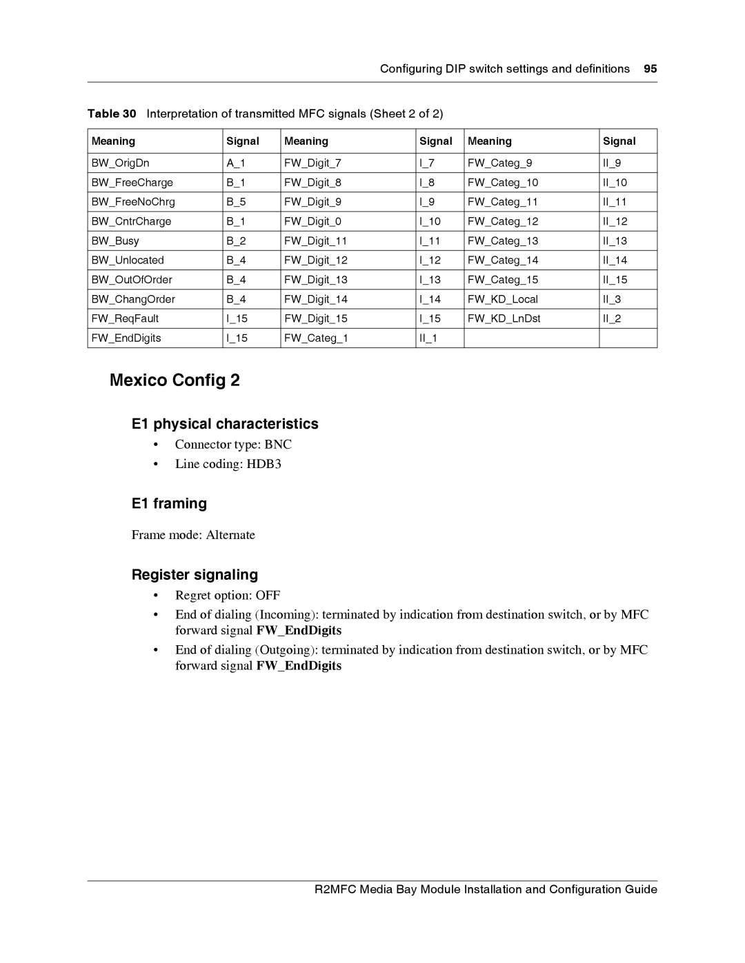
Table 30 Interpretation of transmitted MFC signals (Sheet 2 of 2)
Meaning | Signal | Meaning | Signal | Meaning | Signal |
|
|
|
|
|
|
BW_OrigDn | A_1 | FW_Digit_7 | I_7 | FW_Categ_9 | II_9 |
|
|
|
|
|
|
BW_FreeCharge | B_1 | FW_Digit_8 | I_8 | FW_Categ_10 | II_10 |
|
|
|
|
|
|
BW_FreeNoChrg | B_5 | FW_Digit_9 | I_9 | FW_Categ_11 | II_11 |
|
|
|
|
|
|
BW_CntrCharge | B_1 | FW_Digit_0 | I_10 | FW_Categ_12 | II_12 |
|
|
|
|
|
|
BW_Busy | B_2 | FW_Digit_11 | I_11 | FW_Categ_13 | II_13 |
|
|
|
|
|
|
BW_Unlocated | B_4 | FW_Digit_12 | I_12 | FW_Categ_14 | II_14 |
|
|
|
|
|
|
BW_OutOfOrder | B_4 | FW_Digit_13 | I_13 | FW_Categ_15 | II_15 |
|
|
|
|
|
|
BW_ChangOrder | B_4 | FW_Digit_14 | I_14 | FW_KD_Local | II_3 |
|
|
|
|
|
|
FW_ReqFault | I_15 | FW_Digit_15 | I_15 | FW_KD_LnDst | II_2 |
|
|
|
|
|
|
FW_EndDigits | I_15 | FW_Categ_1 | II_1 |
|
|
|
|
|
|
|
|
Mexico Config 2
E1 physical characteristics
•Connector type: BNC
•Line coding: HDB3
E1 framing
Frame mode: Alternate
Register signaling
•Regret option: OFF
•End of dialing (Incoming): terminated by indication from destination switch, or by MFC forward signal FW_EndDigits
•End of dialing (Outgoing): terminated by indication from destination switch, or by MFC forward signal FW_EndDigits
