Chapter 6 R2MFC MBM maintenance 67
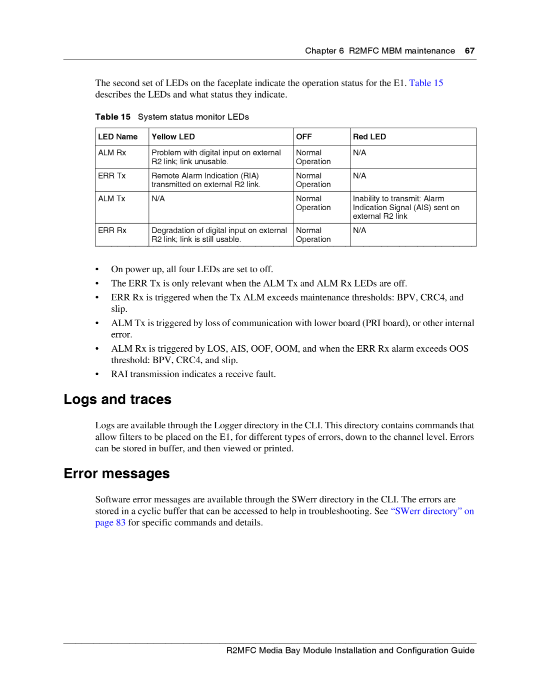
The second set of LEDs on the faceplate indicate the operation status for the E1. Table 15 describes the LEDs and what status they indicate.
Table 15 System status monitor LEDs
LED Name | Yellow LED | OFF | Red LED |
|
|
|
|
ALM Rx | Problem with digital input on external | Normal | N/A |
| R2 link; link unusable. | Operation |
|
|
|
|
|
ERR Tx | Remote Alarm Indication (RIA) | Normal | N/A |
| transmitted on external R2 link. | Operation |
|
|
|
|
|
ALM Tx | N/A | Normal | Inability to transmit: Alarm |
|
| Operation | Indication Signal (AIS) sent on |
|
|
| external R2 link |
|
|
|
|
ERR Rx | Degradation of digital input on external | Normal | N/A |
| R2 link; link is still usable. | Operation |
|
|
|
|
|
•On power up, all four LEDs are set to off.
•The ERR Tx is only relevant when the ALM Tx and ALM Rx LEDs are off.
•ERR Rx is triggered when the Tx ALM exceeds maintenance thresholds: BPV, CRC4, and slip.
•ALM Tx is triggered by loss of communication with lower board (PRI board), or other internal error.
•ALM Rx is triggered by LOS, AIS, OOF, OOM, and when the ERR Rx alarm exceeds OOS threshold: BPV, CRC4, and slip.
•RAI transmission indicates a receive fault.
Logs and traces
Logs are available through the Logger directory in the CLI. This directory contains commands that allow filters to be placed on the E1, for different types of errors, down to the channel level. Errors can be stored in buffer, and then viewed or printed.
Error messages
Software error messages are available through the SWerr directory in the CLI. The errors are stored in a cyclic buffer that can be accessed to help in troubleshooting. See “SWerr directory” on page 83 for specific commands and details.
