94Configuring DIP switch settings and definitions
MFC register signaling
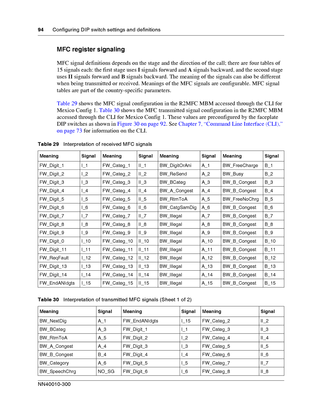
MFC signal definitions depends on the stage and the direction of the call; there are four tables of 15 signals each: the first stage uses I signals forward and A signals backward, and the second stage uses II signals forward and B signals backward. The meaning of the signals can also be different when being transmitted or received. Meanings of the MFC signals are configurable. MFC signal tables are part of the
Table 29 shows the MFC signal configuration in the R2MFC MBM accessed through the CLI for Mexico Config 1. Table 30 shows the MFC transmitted signal configuration in the R2MFC MBM accessed through the CLI for Mexico Config 1. These values are preconfigured by the faceplate DIP switches as shown in Figure 30 on page 92. See Chapter 7, “Command Line Interface (CLI),” on page 73 for information on the CLI.
Table 29 Interpretation of received MFC signals
Meaning | Signal | Meaning | Signal | Meaning | Signal | Meaning | Signal |
|
|
|
|
|
|
|
|
FW_Digit_1 | I_1 | FW_Categ_1 | II_1 | BW_DigitOrAni | A_1 | BW_FreeCharge | B_1 |
|
|
|
|
|
|
|
|
FW_Digit_2 | I_2 | FW_Categ_2 | II_2 | BW_ReSend | A_2 | BW_Busy | B_2 |
|
|
|
|
|
|
|
|
FW_Digit_3 | I_3 | FW_Categ_3 | II_3 | BW_BCateg | A_3 | BW_B_Congest | B_3 |
|
|
|
|
|
|
|
|
FW_Digit_4 | I_4 | FW_Categ_4 | II_4 | BW_A_Congest | A_4 | BW_B_Congest | B_4 |
|
|
|
|
|
|
|
|
FW_Digit_5 | I_5 | FW_Categ_5 | II_5 | BW_RtrnToA | A_5 | BW_FreeNoChrg | B_5 |
|
|
|
|
|
|
|
|
FW_Digit_6 | I_6 | FW_Categ_6 | II_6 | BW_CatgSamDig | A_6 | BW_B_Congest | B_6 |
|
|
|
|
|
|
|
|
FW_Digit_7 | I_7 | FW_Categ_7 | II_7 | BW_Illegal | A_7 | BW_B_Congest | B_7 |
|
|
|
|
|
|
|
|
FW_Digit_8 | I_8 | FW_Categ_8 | II_8 | BW_Illegal | A_8 | BW_B_Congest | B_8 |
|
|
|
|
|
|
|
|
FW_Digit_9 | I_9 | FW_Categ_9 | II_9 | BW_Illegal | A_9 | BW_B_Congest | B_9 |
|
|
|
|
|
|
|
|
FW_Digit_0 | I_10 | FW_Categ_10 | II_10 | BW_Illegal | A_10 | BW_B_Congest | B_10 |
|
|
|
|
|
|
|
|
FW_Digit_11 | I_11 | FW_Categ_11 | II_11 | BW_Illegal | A_11 | BW_B_Congest | B_11 |
|
|
|
|
|
|
|
|
FW_ReqFault | I_12 | FW_Categ_12 | II_12 | BW_Illegal | A_12 | BW_B_Congest | B_12 |
|
|
|
|
|
|
|
|
FW_Digit_13 | I_13 | FW_Categ_13 | II_13 | BW_Illegal | A_13 | BW_B_Congest | B_13 |
|
|
|
|
|
|
|
|
FW_Digit_14 | I_14 | FW_Categ_14 | II_14 | BW_Illegal | A_14 | BW_B_Congest | B_14 |
|
|
|
|
|
|
|
|
FW_EndANIdgts | I_15 | FW_Categ_15 | II_15 | BW_Illegal | A_15 | BW_B_Congest | B_15 |
|
|
|
|
|
|
|
|
Table 30 Interpretation of transmitted MFC signals (Sheet 1 of 2)
Meaning | Signal | Meaning | Signal | Meaning | Signal |
|
|
|
|
|
|
BW_NextDig | A_1 | FW_EndANIdgts | I_15 | FW_Categ_2 | II_2 |
|
|
|
|
|
|
BW_BCateg | A_3 | FW_Digit_1 | I_1 | FW_Categ_3 | II_3 |
|
|
|
|
|
|
BW_RtrnToA | A_5 | FW_Digit_2 | I_2 | FW_Categ_4 | II_4 |
|
|
|
|
|
|
BW_A_Congest | A_4 | FW_Digit_3 | I_3 | FW_Categ_5 | II_5 |
|
|
|
|
|
|
BW_B_Congest | B_4 | FW_Digit_4 | I_4 | FW_Categ_6 | II_6 |
|
|
|
|
|
|
BW_Category | A_6 | FW_Digit_5 | I_5 | FW_Categ_7 | II_7 |
|
|
|
|
|
|
BW_SpeechChrg | NO_SG | FW_Digit_6 | I_6 | FW_Categ_8 | II_8 |
|
|
|
|
|
|