Manuals
/
Outback Power Systems
/
TV and Video
/
Flat Panel Television
Outback Power Systems
80 12V Battery System Efficiency Curve, 24V Battery System Efficiency Curve
Models:
80
1
62
92
92
Download
92 pages
41.02 Kb
59
60
61
62
63
64
65
66
Page 62
Image 62
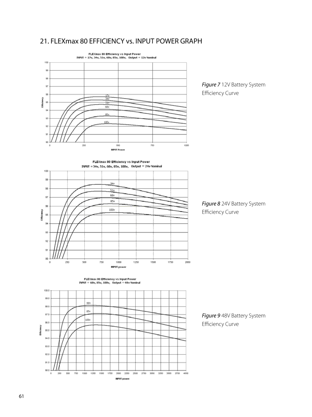
21. FLEXmax 80 EFFICIENCY vs. INPUT POWER GRAPH
Figure 7
12V Battery System
Efficiency Curve
Figure 8
24V Battery System
Efficiency Curve
Figure 9
48V Battery System
Efficiency Curve
61
Page 61
Page 63
Page 62
Image 62
Page 61
Page 63
Contents
User’s Guide
Warranty Summary
Dear OutBack Customer
Date and Revision
About OutBack Power Systems
Disclaimer
Contact Information
Table of Contents
Product Registration and Optional Extended Warranty
Introduction
FLEXmax 80 Maximum Power Point Tracking Charge Controller
Scope
Firmware
Standards and Requirements
Personal Precautions During Installation
Outback Power Systems FLEXmax
DC Enclosure FLEXmax Bushing Locknut Conduit Nipple
Installing the FLEXmax 80 FLEXware DC Enclosures
Mounting to Plywood
Open Circuit Voltage/Wire and Disconnect Size
Determining Wire Sizes
Wire and Disconnect Sizing
FLEXmax 80 Wiring Connections
FLEXmax 80 wiring compartment
Page
Page
Page
How to Read the FLEXmax 80 Screen Diagrams
Soft keys
OutBack12V Power Systems FLEXmax
Powering Up
Power Up Screen
USA Next Enter Entra SEL
Password Contrasena
Select Version Elija la Version
150
Enter
USA Noyes
Sytem Voltage
Status Screen
AUX OFF
Recharging Using the PV Array
End of Day Summary Screen
Exit F G GO
Accessing the Main Menu
Charger Aux Light EQ Misc Advanced Logging Stats
80.0A
Charger Set-Up
Current Limit
Absorbing 14.4V Float 13.8V
Exit Next SET Mode
AUX Mode and Its Functions
AUX Mode
Night Light Output Off
AUX Mode Menu Path
Pressing the Next soft key scrolls through the AUX functions
AUX modes in order of appearance on the FLEXmax 80 display
Vent Fan
Programming the AUX Modes
Off
Exitvolt Vent FAN Volts
PV Trigger Output Off
Exit Volt
Exit Next SET
Fan screen
Exit Time Volt PV Volts
Output On
PV Trigger
Exit Time Volt
PV Trigger Output On
Press the Next soft key to view the Error Output screen
Hold Time Sec 01.1 Back +
Exitvolt AUX Mode Error Output
Error Output 01 hrs
Exitvolt Error LOW Batt Volts
Back + OFF
Exit Next SET Mode AUX Mode
Exit Hyst Time Volt
Night Light Threshold Voltage 010 Back +
Night Light Off Hysteresis Time Minutes Back +
Night Light On Time Hours Back +
Press the Volt soft key
Diversion Relay Output Off
Output Off Auto
Float Output Off
Press the Next soft key ro view the AUX Float screen
Diversion Relay
Hold Delay 01.0 Time Seconds
Back DLY+ AUX Mode
Absorb--Float--EQ Relative Volts
Example of Diversion
Exit Time Volt AUX Mode
Diversion Solid St Output On
Press the Exit soft key
Diversion Load and AUX Wiring Set-Up Illustrated
Low Batt Disconnect
Delay Time Sec Timer Back +
Press the Time and Volt soft keys to adjust the set points
RE-CONNECT Volts
Exit Time Volt Disconnect Volts
Back
Logging Stats
Remote Output Off
Charger GAux Light Misc
Exit soft key twice to return to the Main Menu Off screen
Backlight
EQ-Battery Equalize
Exit + Mode
Charger Aux GLight EQ Misc Optimize Logging Stats
Exit Next -HRS +HRS Battery Equalize
Battery Equalize
Exit Next -EQV +EQV Battery Equalize
Back Auto Start Stop
Exit DAY +DAY
Count
000
Exit Next -EQV +EQV
Exit Next
MISC-Miscellaneous
GT State PWM% ChgT 255 07 50.0
Press Next to Continue to the Force Bulk/Float Screen
Exit Next Float Bulk
PWM%
Force
PCB
Charger Aux Light Misc GAdvanced Logging Stats
Snooze Mode .6 amp
Advanced
Exit Advanced Menu
This screen allows the user to choose one of these modes
Wakeup Mode 1.5V 05m Exit Next +VOC +Min
Mppt Mode Auto Track Exit Next nonGT Mode
Press the Next soft key to view the Park Mpp screen
Mpp Range Limit %Voc Min Max Exit Next 1/2 90%
Park Mpp 77 % Voc
Exit Next -% +% Advanced Menu
Park Mpp Watts 77 % Voc
Exit Next +
Charging-Related Screens
Advanced Menu Absorb Time Limits Hours
00 a
12.6
Exit Next Wide Advanced Menu
Vbatt Calibration 14.1
RTS Compensation 14.1
Exit Next Limit SET RTS Compensation
RTS Compensation 14.4 V F
Mode Exit Next Mode Advanced Menu
Mode Exit Next Mode
Exit Next Limit SET
Aux Polarity
Exit Next Mode Advanced Menu
Reset to Defaults?
Charger
Are you sure? Reset to Defaults
Yesno Advanced Menu
GLogging Stats
Today 0000Ah 00.0 KWH 011Vp 00.0Ap 00kWp MAX
Logging
Clear LOG Back Totl Daily
MIN FLT
Stats
Secondary Stats screen
Warranty its use in these applications
Micro-Hydro and Fuel Cell Applications
Advanced Menu Micro-Hydro and Fuel Cell Applications
Mppt Mode Auto Track
To adjust the Lower Mpp Range Limit
Park Mpp Watts
Abbreviated Menu Map
Grid-tie applications non-OutBack inverter/chargers
OutBack Power System GTFX/GVFX Grid-tie settings
Application Notes
Positive grounded systems
12V Battery System Efficiency Curve
24V Battery System Efficiency Curve
Understanding the Various Operational Modes
Page
Page
MATE-Displayed FLEXmax 80 Screens Status Mode Screens
Aux relay state indicates if the AUX is on or OFF
Press Setp to view Setpoint screens
MATE-Displayed FLEXmax 80 Status Meter Screens
FLEXmax Meter Screens
CC Setpoint Screens
MATE-Displayed FLEXmax 80 Status Setpt SET Point Screen
MATE-Displayed FLEXmax 80 Advanced Screens
FLEXmax 80 Advanced Menu
FLEXmax 80 Displayed Screens
FLEXmax 80 EQ Screens
FLEXmax 80 AUX Screens
FLEXmax 80 Stats Screens
Abbreviated
Exit Next + Advanced Menu
FLEXmax 80 not producing expected power
Troubleshooting Guide
FLEXmax 80 does not boot/power-up blank LCD
FLEXmax 80 is always Sleeping
FLEXmax 80 Battery Temperature Compensated Voltage
FLEXmax 80 is not equalizing
FLEXmax 80 is beeping
To enable/open the FLEXmax Select Version screens
FLEXmax 80 Internal Fan
Typical Array Sizing Guide
Standard vs. Australian Default Settings
24V PV Array 32v Vmp
Wire Distance Chart
12V PV Array 16v Vmp
36V PV Array 48v Vmp
72V PV Array 96v Vmp
48V PV Array 64v Vmp
60V PV Array 80v Vmp
PV Side of the Controller
Wire and Disconnect Sizing
Battery Side of the Controller
NEC Compliance
Recommended Conductor and Breaker Sizes for the FLEXmax
Wiring Compartment
Maximum recommended battery conductor is #2** AWG
Output Rating less than 64 amps
FLEXmax 80 MULTI-STAGE Battery Charging
Page
Battery temperature compensation with other slopes
Non-Battery Temperature Compensated System
Battery Temperature Compensated System
Suggested Battery Charger SET Points
Battery Voltage and State of Charge
Specifications
Calling the Factory for Assistance
Five Year Limited Warranty Information
FLEXmax Products
Revision.2007-10-02
Limited Warranty Registration
Outback Power Systems Inc 19009 62nd Ave. NE
EU Declaration of Conformity
OWNER’S System Information
Phone +1 BARCELONA, España Phone +34.93.654.9568
Top
Page
Image
Contents