Installation and Maintenance Guide
BitStorm 1900 IP Dslam
Copyright 2002 Paradyne Corporation All rights reserved
Important Safety Instructions
United States EMI Notice
Table of Contents
BitStorm 1900 Installation and Testing
BitStorm 1900 Maintenance
Appendix B. Cabling Specifications
List of Figures
21 Voice/Data System Test Points
List of Tables
1900-A2-GN20-00
Focus and Audience
Related Documents
Conventions
ENTER, Name, Tab, programs\seven\aa1
1900-A2-GN20-00
BitStorm 1900 System Components
Introduction
Product Overview
BitStorm 1900 Shelf
BitStorm 1900 Shelf with Cards and Components
Filter Shelf Option
Air Baffle
Fan Tray
Configuration Number of Filter Shelves
Filter 66-Block Option
Filter 66-Block
CO Modem Cards
Privacy Management
CO Modem Card LEDs
Color
Same Card Broadcast
Enabled Feature Function Security
Disabled
Spectrum Manager-Video Protect
Mode Description
Spectrum Manager Adsl Protect
MIU Snmp Functionality
WAN Interface Cards
Passes Vlan Tagged Frames
Mixing CO Modem Cards
StormPort CPE Modems
CO Modem Card
Mbps CO Modem Card Specifications
Special Features
BitStorm 1900 with 10306 Modem Cards
System Power Specifications with 10306 CO Modem
CO Modem IP Multicast Operation
10306 IP Multicast Operation
BitStorm 1900 IP Dslam
CO Modem Card
BitStorm 1900 with 10224 Modem Cards
System Power Specifications with 10224 CO Modem
WAN Interface Card Specifications
MIU Management Interface Unit
BitStorm 1900 with MIU 01-00075-01 and 10306 CO Modems
Hospitality /VBN Carrier
Power Card Specifications
260 W DC Power Card
BitStorm 1900 IP Dslam
260 W AC Power Card
Fan Tray 110/220 V AC
Fan Tray Specifications
Fan Tray 110/220 V AC Specifications
Power Specifications for the AC Fan Tray
Fan Tray -48 V DC
Fan Tray -48 V DC Specifications
Power Specifications for the DC Fan Tray
Filter 66-Block
Low-Pass Filter Specifications
Filter Shelf
Filter Shelf Specifications
Filter 66-Block Specifications
BitStorm 1900 Component Requirements
BitStorm 1900 Component Requirements
1900-A2-GN20-00
BitStorm 1900 Installation and Testing
Installation Flowchart
BitStorm 1900 Installation Flowchart
Task # and Description
Installation Task List
Installing the BitStorm
Tools, Equipment, and Materials
Task 001 Pre-Installation Checklist
Installation Tools, Equipment, and Materials
Rxkdyhfrpsohwhgwklvwdvn
Task 002 Installing the 19 Fan Tray
Fan Tray Mounting
48 V DC Fan Tray
Rxkdyhfrpsohwhgwklvwdvn
Task 003 Installing the BS1900 and Filter Shelves
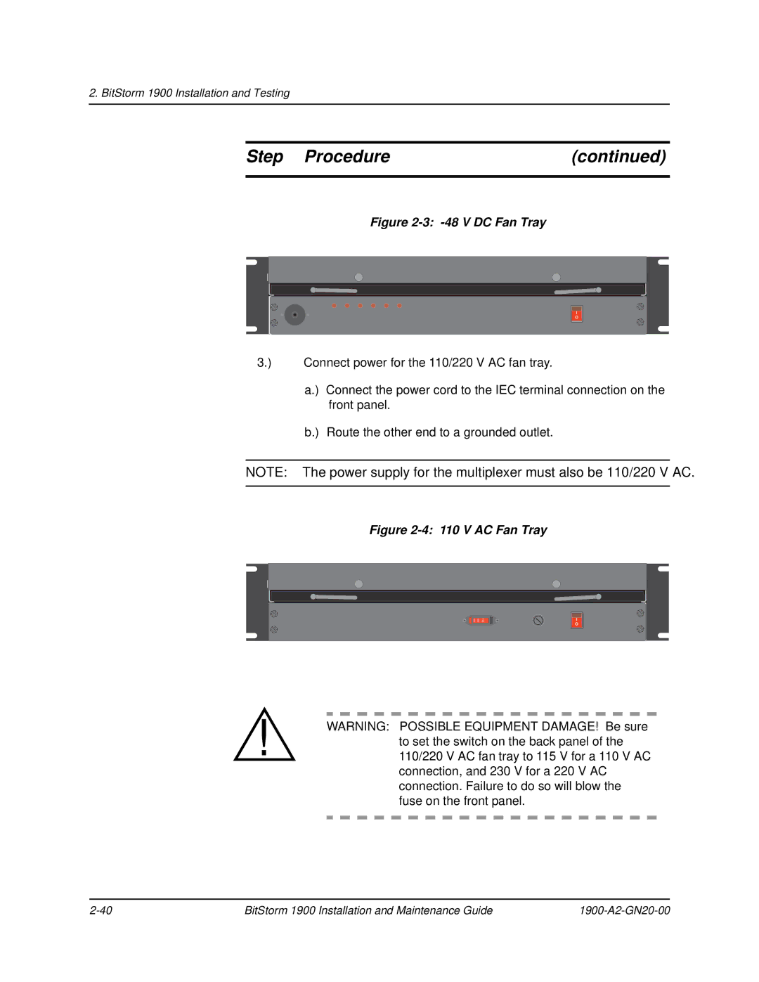
Step Procedure
BitStorm 1900 Modem Shelves Mounted in Bay
BitStorm 1900 Shelf Fastened to Bay
If the application is Then
Filter Shelf Mounting in Bay
Task 004 Installing the Air Baffle
Task 005 Installing the Circuit Packs
Task 006 Connecting Power to the Shelf
Power Power Source Terminal Connection Line Fuse
Lead
Single Power Source
Typical Power Connection to 260W AC Power Source
Rxkdyhfrpsohwhgwklvwdvn
Cable Requirements Application
Task 007 Installing the Data Network Connection with an MIU
Data Cable Selection for MIU Shelf Processor
Hospitality /VBN
11 MIU Card with Cable Connections
Task 008 Installing Voice/Data & Filter Shelf
Task 008 Installing Voice/Data & Filter Shelf Connections
Pin and Pair Assignments for the Champ to Omni Grid Cable
Step Procedure
J3 J2 J3 J2 *Not Used
Omni Grid to
Rxkdyhfrpsohwhgwklvwdvn
Task 009 Installing Voice/Data w/Filter 66-Block Connections
02-17186
Amp Champ to Dual Omni Grid Cable Not Used
Task 010 Installing the Data-only Connections
17,Data-only Connections on the 66-Block for 10224 CO
Female Male Amp Champ to Dual Omni Grid Cable Not Used
Task 011 Installing External Voice Switch Connections
Step Procedure
Task 012 Configuring the MIU
18 Craft Connection with the MIU Craft Cable
19 COM Port Settings
Step Procedure
Command Description
CLI Command Line Interface Commands
CLI Commands
Date
CLI Commands Description
Reset of the system
BitStorm 1900 MIU Craft Interface Main
Network Interface Configuration screen
Step Procedure
User Account Administration
Step Procedure
Key to return to the User Account Administration
Step Procedure
Type a to select Reset System, and then y to confirm
Task 013 Configuring Remote Management
20 Telnet Connection for the BitStorm
Using Snmp Network Management Software
Step Procedure
Enter
Step Procedure
Ifconfig -m 0 and press Enter
To edit the Snmp configuration information type snmp -m
To view the current Snmp parameters, type snmp -Land press
Setting Description
Current Poll Interval, and Set Trap Targets
Rxkdyhfrpsohwhgwklvwdvn
Task 014 Testing the BitStorm 1900 Installation
Review the BitStorm 1900 Test Point Diagrams as follows
PBX
22 Data-only System Test Points
Task 015 Testing Voice Connectivity
Task 016 Testing Data Connectivity
Task 017 EtherLoop End-to-End Testing
BitStorm 1900 Maintenance on page 103 for more information
Maintenance Guidelines
Wiring Conditions
BitStorm 1900 Equipment Installation
Data Network Equipment Configuration
Cable Connections
Equipment Failure
Maintenance Checklists
Voice/Data Connectivity Troubleshooting Checklist
Voice/Data Connectivity Maintenance in Facility Room
Problem Maintenance Check
Problem Check
End-to-End Maintenance Checklist
End-to-End Maintenance Checklist
Bay Requirements and Specifications
BitStorm 1900 Support Equipment
BS1900 System Specifications
Table A-1 BitStorm 1900 System Specifications
Grounding Environment Specifications
Fan Trays
CBN Grounding Environment
IBN Grounding Environment
BS1900 Component Installation Requirements
Network Support Equipment
Table A-2 BitStorm 1900 Components
Part# BitStorm Component Rules/Capacity
Installation Tools and Materials
BitStorm 1900 Physical Characteristics
Installation Site Requirements
Table A-3 BitStorm 1900 Weight and Dimensions
Specification Weight metric
Specification Requirement
Table A-4 BitStorm Operational Requirements
Appendix B. Cabling Specifications
Cable Connections and Specifications
Modem Card Cabling
Figure B-1 Cabling Filter Shelf with 10306 Modem Cards
Figure B-2 Cabling Filter 66-Block with 10306 Modem Cards
Figure B-3 Cabling Filter Shelf with 10224 Modem Cards
BitStorm 1900 Cable Harness
Figure B-4 Cabling Filter 66-Block with 10224 Modem Cards
Decapus Cable
Figure B-5 Decapus Cable Connections
AMP-Champ to Dual AMP Champ Cable
Figure B-6 AMP Champ to Dual AMP Champ Cable
Conn1 Color Code Conn3 Cable
Table B-1 AMP-Champ to Dual AMP-Champ Cable Specifications
Conn1 Color Code Conn2 Cable
AMP Champ to Dual Omni Grid Cable
Figure B-7 AMP Champ to Dual Omni Grid Cable
Table B-2 AMP Champ to Dual Omni Grid Cable Specifications
Omni Grid to Dual Omni Grid
Figure B-8 Omni Grid to Dual Omni Grid Cable
Table B-3 Omni Grid to Dual Omni Grid Cable Specifications
Omni Grid to Omni Grid Cable
Figure B-9 Omni Grid to Omni Grid Cable
Table B-4 Omni Grid to Omni Grid Cable Specifications
Intermediate Cable Specifications
Figure B-10 Intermediate Cable
Power Cable Harness
Power Connector Terminations
Table B-5 Terminal Connection for DC Power Source
Power Cable Power Source Terminal Connection Connector
131
1900-A2-GN20-00
Main Menu
Figure C-1 Main Menu
Configuration
Figure C-2 A. Configuration Configuration Menu
Figure C-4 A. Configuration B. Snmp Configuration Menu
Figure C-7 A. Configuration C. Set Time-of-Day Clock
Statistics
Figure C-8 B. Statistics Menu
Figure C-10 B. Statistics B. Physical Layer Statistics Menu
Figure C-13 B. Statistics C. Environment Statistics
Figure C-14 B. Statistics D. System Memory Statistics
Figure C-16 B. Statistics F. System Error-Reset Data
User Account Administration
Firmware Version Information
143
Figure C-23 E. Utilities A. Reset Confirmation
Figure C-22 E. Utilities Menu