Installation
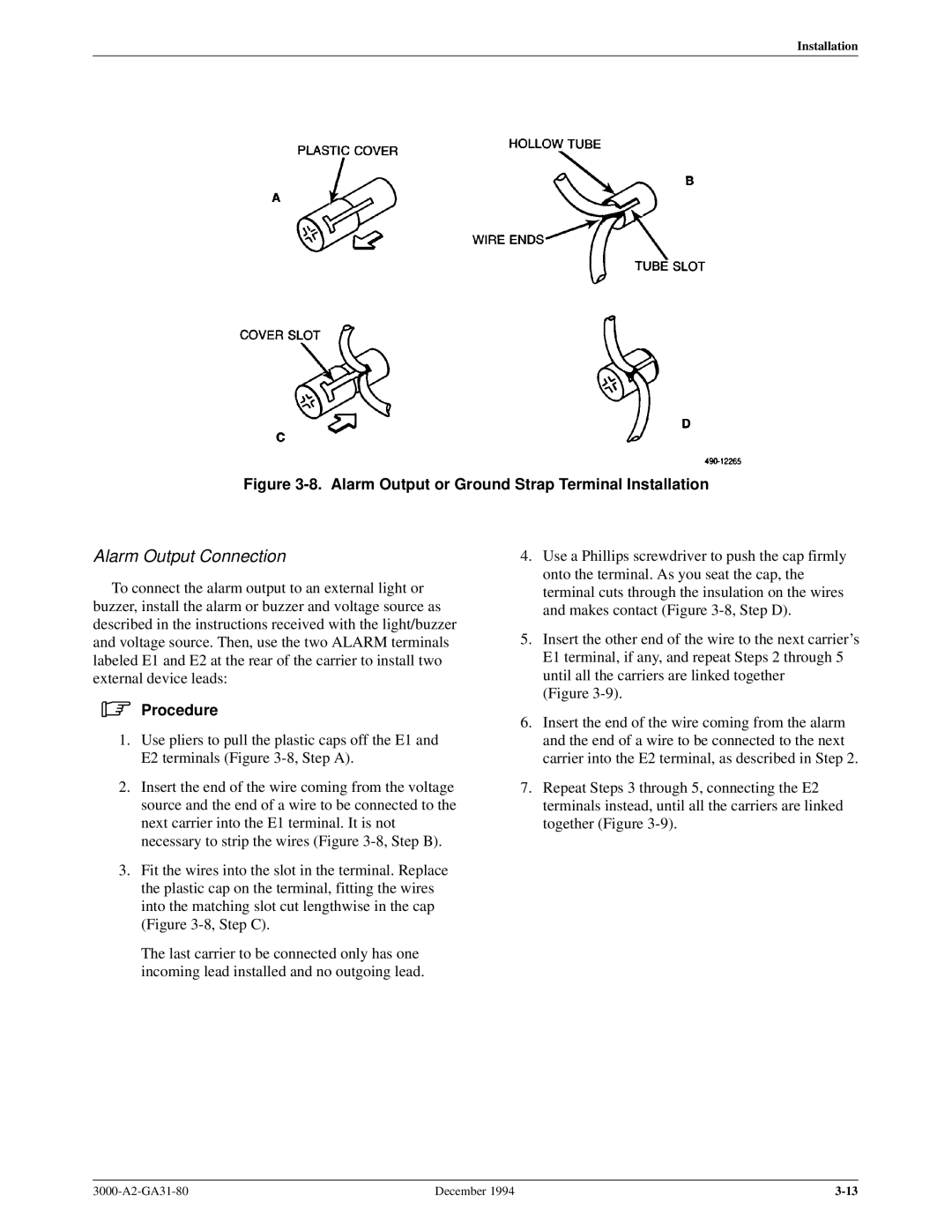
Figure 3-8. Alarm Output or Ground Strap Terminal Installation
Alarm Output Connection
To connect the alarm output to an external light or buzzer, install the alarm or buzzer and voltage source as described in the instructions received with the light/buzzer and voltage source. Then, use the two ALARM terminals labeled E1 and E2 at the rear of the carrier to install two external device leads:
.Procedure
1.Use pliers to pull the plastic caps off the E1 and E2 terminals (Figure
2.Insert the end of the wire coming from the voltage source and the end of a wire to be connected to the next carrier into the E1 terminal. It is not necessary to strip the wires (Figure
3.Fit the wires into the slot in the terminal. Replace the plastic cap on the terminal, fitting the wires into the matching slot cut lengthwise in the cap (Figure
The last carrier to be connected only has one incoming lead installed and no outgoing lead.
4.Use a Phillips screwdriver to push the cap firmly onto the terminal. As you seat the cap, the terminal cuts through the insulation on the wires and makes contact (Figure
5.Insert the other end of the wire to the next carrier's E1 terminal, if any, and repeat Steps 2 through 5 until all the carriers are linked together
(Figure
6.Insert the end of the wire coming from the alarm and the end of a wire to be connected to the next carrier into the E2 terminal, as described in Step 2.
7.Repeat Steps 3 through 5, connecting the E2 terminals instead, until all the carriers are linked together (Figure
December 1994 |