Installation
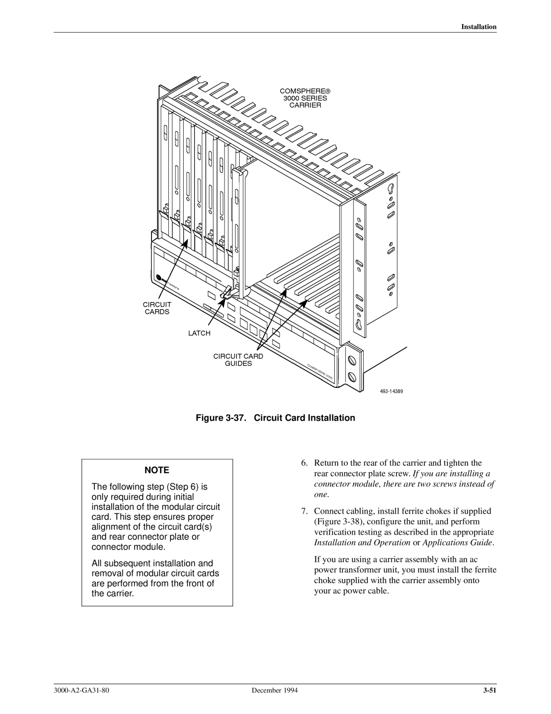
Figure 3-37. Circuit Card Installation
NOTE
The following step (Step 6) is only required during initial installation of the modular circuit card. This step ensures proper alignment of the circuit card(s) and rear connector plate or connector module.
All subsequent installation and removal of modular circuit cards are performed from the front of the carrier.
6.Return to the rear of the carrier and tighten the rear connector plate screw. If you are installing a connector module, there are two screws instead of one.
7.Connect cabling, install ferrite chokes if supplied (Figure
If you are using a carrier assembly with an ac power transformer unit, you must install the ferrite choke supplied with the carrier assembly onto your ac power cable.
December 1994 |