COMSPHERE Interface A Connections
Overview . . . . . . . . . . . . . . . . . . . . . . . . . . . . . . . . . . . . . . . . . . . . . . . . . . . . . . . . . . . . . . . . . . . . . . . . . .
Overview
Two
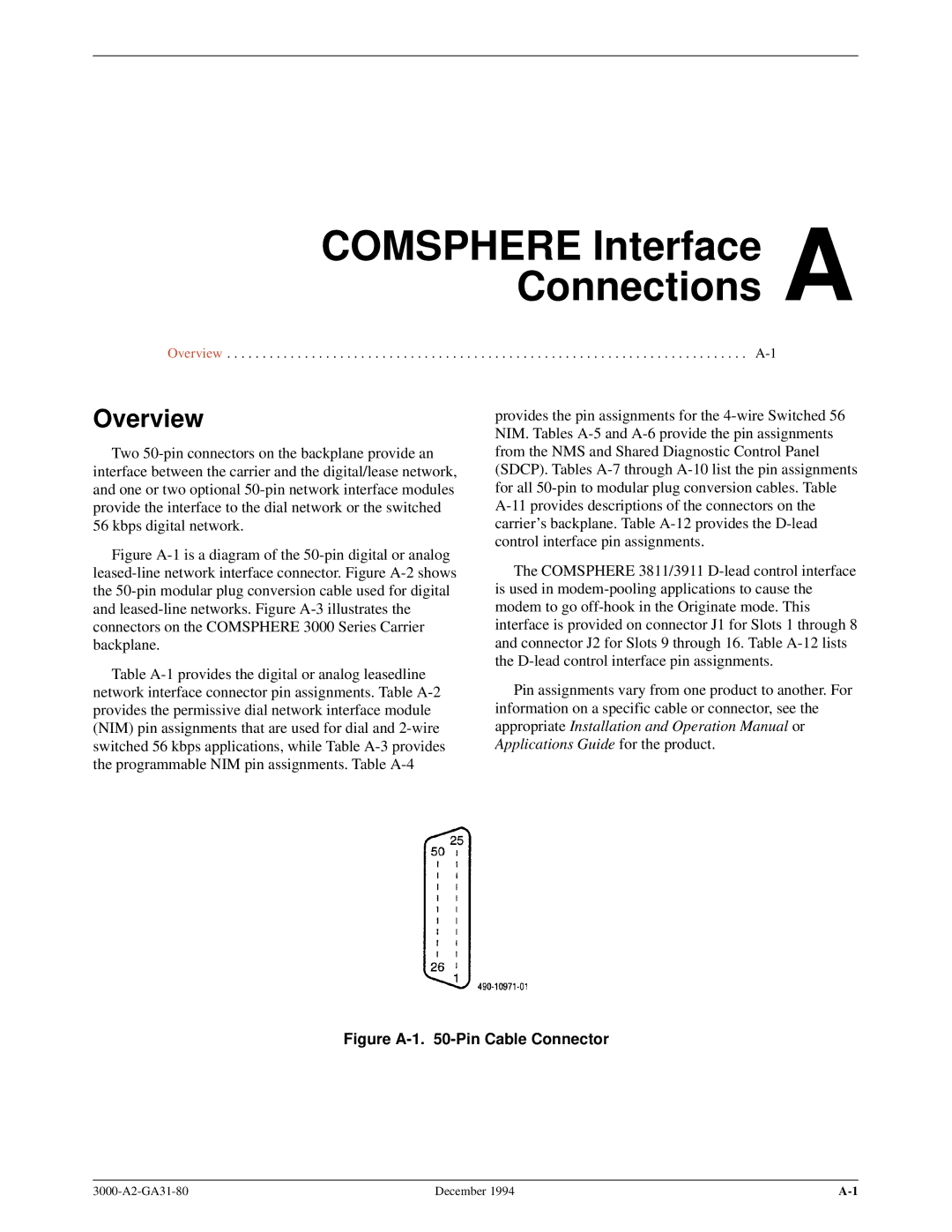
Figure A-1 is a diagram of the 50-pin digital or analog leased-line network interface connector. Figure A-2 shows the 50-pin modular plug conversion cable used for digital and leased-line networks. Figure A-3 illustrates the connectors on the COMSPHERE 3000 Series Carrier backplane.
Table A-1 provides the digital or analog leasedline network interface connector pin assignments. Table A-2 provides the permissive dial network interface module (NIM) pin assignments that are used for dial and 2-wire switched 56 kbps applications, while Table A-3 provides the programmable NIM pin assignments. Table A-4
provides the pin assignments for the 4-wire Switched 56 NIM. Tables A-5 and A-6 provide the pin assignments from the NMS and Shared Diagnostic Control Panel (SDCP). Tables A-7 through A-10 list the pin assignments for all 50-pin to modular plug conversion cables. Table A-11 provides descriptions of the connectors on the carrier's backplane. Table A-12 provides the D-lead control interface pin assignments.
The COMSPHERE 3811/3911 D-lead control interface is used in modem-pooling applications to cause the modem to go off-hook in the Originate mode. This interface is provided on connector J1 for Slots 1 through 8 and connector J2 for Slots 9 through 16. Table A-12 lists the D-lead control interface pin assignments.
Pin assignments vary from one product to another. For information on a specific cable or connector, see the appropriate Installation and Operation Manual or Applications Guide for the product.
Figure A-1. 50-Pin Cable Connector
December 1994 |