Paradyne 3000 manual SDU NMS, A-4

Models: 3000

1 131
Download 131 pages 24.91 Kb
Page 129
Image 129

COMSPHERE 3000 Series Carrier

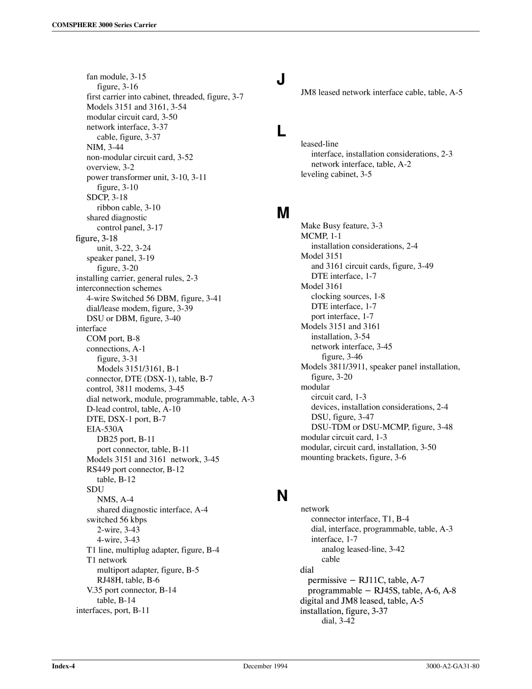
fan module, 3-15 figure, 3-16

first carrier into cabinet, threaded, figure, 3-7 Models 3151 and 3161, 3-54

modular circuit card, 3-50 network interface, 3-37

cable, figure, 3-37 NIM, 3-44

non-modular circuit card, 3-52 overview, 3-2

power transformer unit, 3-10, 3-11 figure, 3-10

SDCP, 3-18

ribbon cable, 3-10 shared diagnostic

control panel, 3-17 figure, 3"18

unit, 3-22, 3-24 speaker panel, 3-19

figure, 3-20

installing carrier, general rules, 2-3 interconnection schemes

4-wire Switched 56 DBM, figure, 3-41 dial/lease modem, figure, 3-39

DSU or DBM, figure, 3-40 interface

COM port, B-8 connections, A-1 figure, 3-31

Models 3151/3161, B-1 connector, DTE (DSX-1), table, B-7 control, 3811 modems, 3-45

dial network, module, programmable, table, A-3 D-lead control, table, A-10

DTE, DSX-1 port, B-7 EIA-530A

DB25 port, B-11

port connector, table, B-11 Models 3151 and 3161 network, 3-45 RS449 port connector, B-12

table, B-12

SDU NMS, A-4

shared diagnostic interface, A-4 switched 56 kbps

2-wire, 3-43

4-wire, 3-43

T1 line, multiplug adapter, figure, B-4

T1 network

multiport adapter, figure, B-5 RJ48H, table, B-6

V.35 port connector, B-14 table, B-14

interfaces, port, B-11

J

JM8 leased network interface cable, table, A-5

L

leased-line

interface, installation considerations, 2-3 network interface, table, A-2

leveling cabinet, 3-5

M

Make Busy feature, 3-3 MCMP, 1-1

installation considerations, 2-4 Model 3151

and 3161 circuit cards, figure, 3-49 DTE interface, 1-7

Model 3161

clocking sources, 1-8 DTE interface, 1-7 port interface, 1-7

Models 3151 and 3161

installation, 3-54 network interface, 3-45

figure, 3-46

Models 3811/3911, speaker panel installation, figure, 3-20

modular

circuit card, 1-3

devices, installation considerations, 2-4 DSU, figure, 3-47

DSU-TDM or DSU-MCMP, figure, 3-48 modular circuit card, 1-3

modular, circuit card, installation, 3-50 mounting brackets, figure, 3-6

N

network

connector interface, T1, B-4

dial, interface, programmable, table, A-3 interface, 1-7

analog leased-line, 3-42 cable

dial

permissive - RJ11C, table, A"7 programmable - RJ45S, table, A"6, A"8

digital and JM8 leased, table, A"5 installation, figure, 3"37

dial, 3-42

Index-4

December 1994

3000-A2-GA31-80

Page 129
Image 129
Paradyne 3000 manual SDU NMS, A-4