Installation
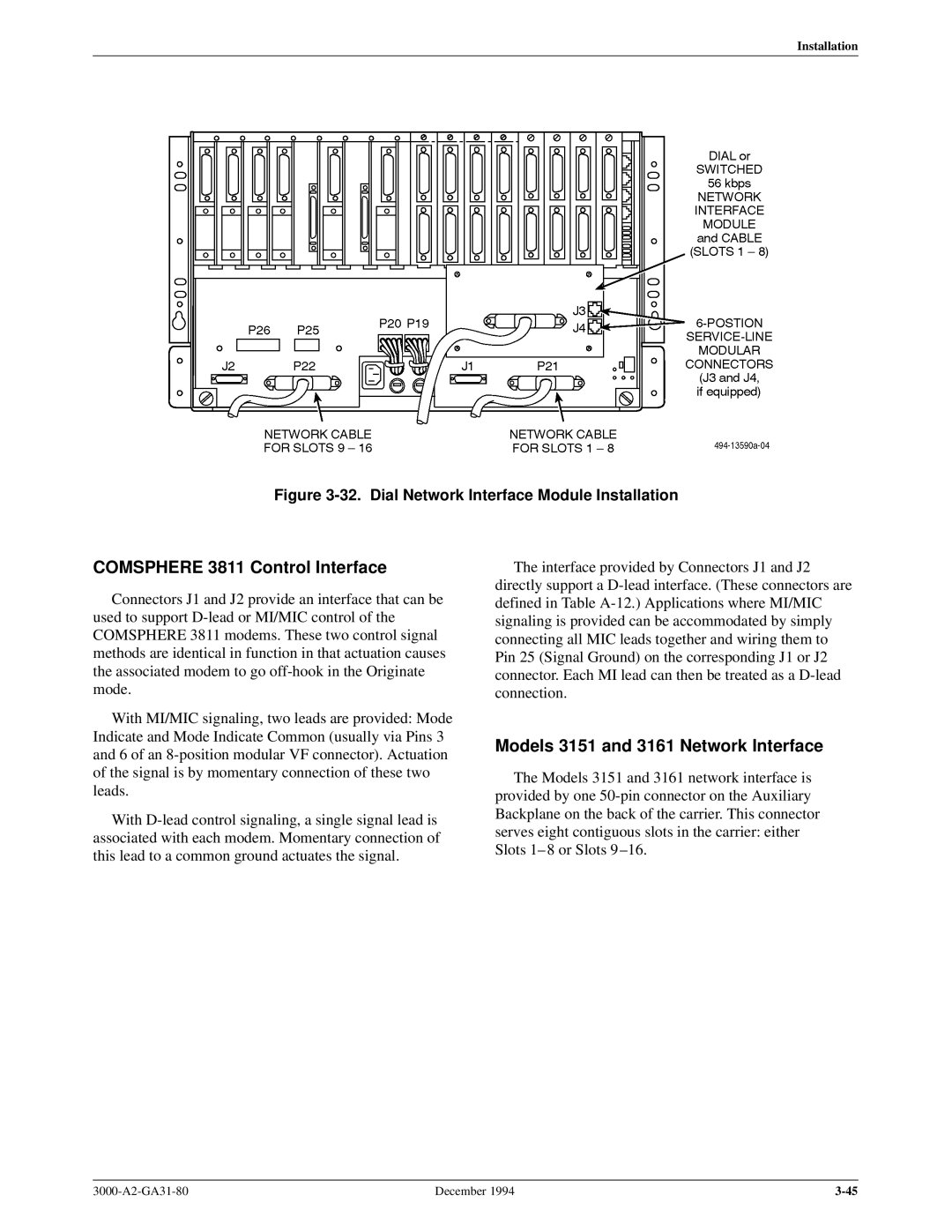
Figure 3-32. Dial Network Interface Module Installation
COMSPHERE 3811 Control Interface
Connectors J1 and J2 provide an interface that can be used to support D-lead or MI/MIC control of the COMSPHERE 3811 modems. These two control signal methods are identical in function in that actuation causes the associated modem to go off-hook in the Originate mode.
With MI/MIC signaling, two leads are provided: Mode Indicate and Mode Indicate Common (usually via Pins 3 and 6 of an 8-position modular VF connector). Actuation of the signal is by momentary connection of these two leads.
With D-lead control signaling, a single signal lead is associated with each modem. Momentary connection of this lead to a common ground actuates the signal.
The interface provided by Connectors J1 and J2 directly support a D-lead interface. (These connectors are defined in Table A-12.) Applications where MI/MIC signaling is provided can be accommodated by simply connecting all MIC leads together and wiring them to Pin 25 (Signal Ground) on the corresponding J1 or J2 connector. Each MI lead can then be treated as a D-lead connection.
Models 3151 and 3161 Network Interface
The Models 3151 and 3161 network interface is provided by one 50-pin connector on the Auxiliary Backplane on the back of the carrier. This connector serves eight contiguous slots in the carrier: either Slots 1± 8 or Slots 9 ±16.
3000-A2-GA31-80 | December 1994 | 3-45 |