COMSPHERE 3000 Series Carrier
NIM Installation
To install the NIM providing the dial interface for the dial backup devices (DBMs), dial/lease modems, or the switched 56 kbps network interface for either the
.Procedure
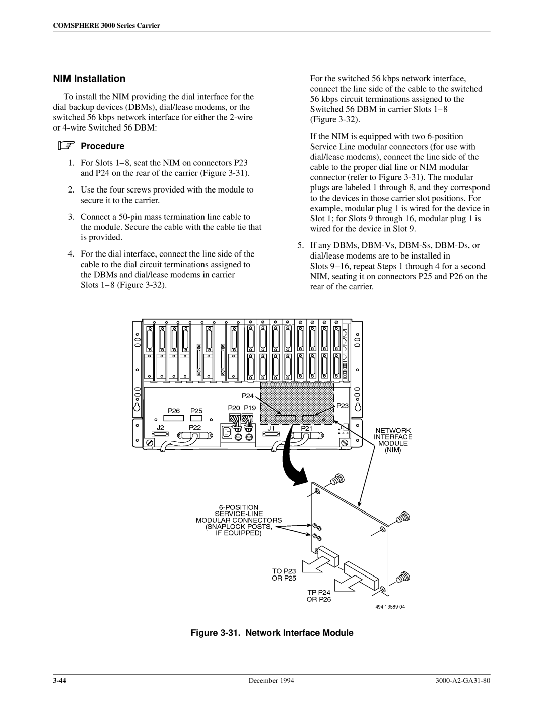
1.For Slots 1± 8, seat the NIM on connectors P23 and P24 on the rear of the carrier (Figure
2.Use the four screws provided with the module to secure it to the carrier.
3.Connect a
4.For the dial interface, connect the line side of the cable to the dial circuit terminations assigned to the DBMs and dial/lease modems in carrier Slots 1± 8 (Figure
For the switched 56 kbps network interface, connect the line side of the cable to the switched 56 kbps circuit terminations assigned to the Switched 56 DBM in carrier Slots 1± 8 (Figure
If the NIM is equipped with two
5.If any DBMs,
Slots 9 ±16, repeat Steps 1 through 4 for a second NIM, seating it on connectors P25 and P26 on the rear of the carrier.
Figure 3-31. Network Interface Module
December 1994 |