Overview
A COMSPHERE 72-inch cabinet is available for mounting the COMSPHERE 3000 Series Carriers. Up to six carriers can be mounted into a single cabinet. The COMSPHERE 3000 Series Carriers can also be mounted into other commercial EIA standard 19-inch and 23-inch cabinets.
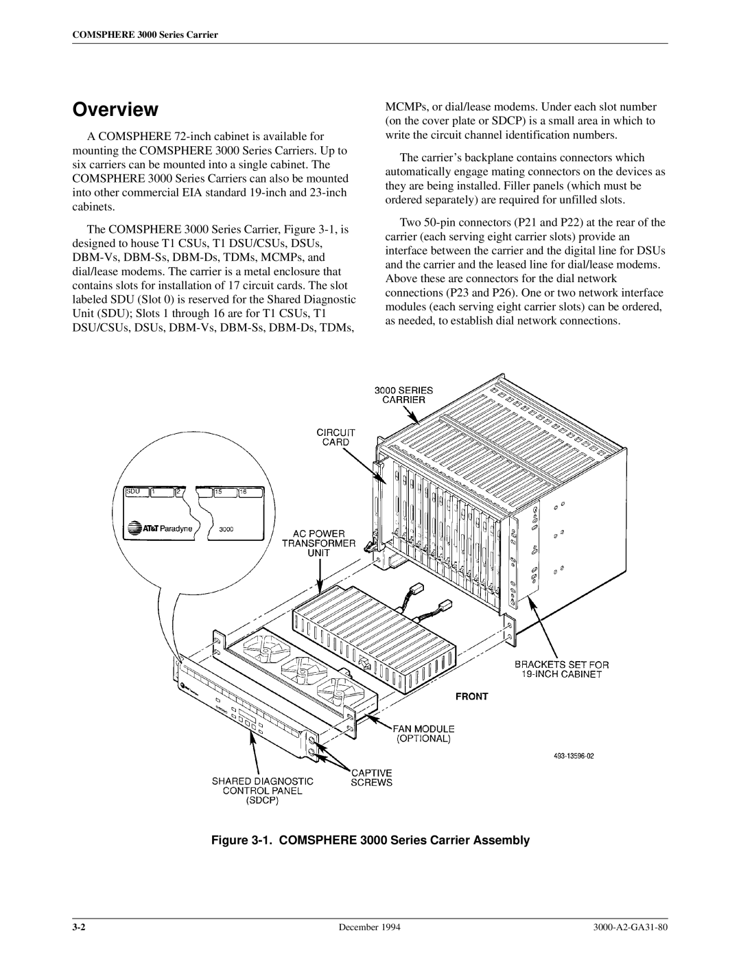
The COMSPHERE 3000 Series Carrier, Figure 3-1, is designed to house T1 CSUs, T1 DSU/CSUs, DSUs, DBM-Vs, DBM-Ss, DBM-Ds, TDMs, MCMPs, and dial/lease modems. The carrier is a metal enclosure that contains slots for installation of 17 circuit cards. The slot labeled SDU (Slot 0) is reserved for the Shared Diagnostic Unit (SDU); Slots 1 through 16 are for T1 CSUs, T1 DSU/CSUs, DSUs, DBM-Vs, DBM-Ss, DBM-Ds, TDMs,
MCMPs, or dial/lease modems. Under each slot number (on the cover plate or SDCP) is a small area in which to write the circuit channel identification numbers.
The carrier's backplane contains connectors which automatically engage mating connectors on the devices as they are being installed. Filler panels (which must be ordered separately) are required for unfilled slots.
Two 50-pin connectors (P21 and P22) at the rear of the carrier (each serving eight carrier slots) provide an interface between the carrier and the digital line for DSUs and the carrier and the leased line for dial/lease modems. Above these are connectors for the dial network connections (P23 and P26). One or two network interface modules (each serving eight carrier slots) can be ordered, as needed, to establish dial network connections.