Models 3151/3161 Interface Connections
Table B-1
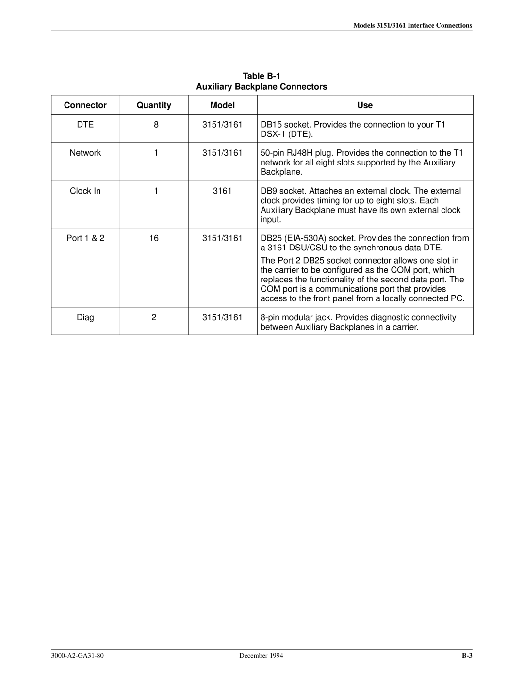
Auxiliary Backplane Connectors
Connector | Quantity | Model | Use |
|
|
|
|
DTE | 8 | 3151/3161 | DB15 socket. Provides the connection to your T1 |
|
|
| |
|
|
|
|
Network | 1 | 3151/3161 | |
|
|
| network for all eight slots supported by the Auxiliary |
|
|
| Backplane. |
|
|
|
|
Clock In | 1 | 3161 | DB9 socket. Attaches an external clock. The external |
|
|
| clock provides timing for up to eight slots. Each |
|
|
| Auxiliary Backplane must have its own external clock |
|
|
| input. |
|
|
|
|
Port 1 & 2 | 16 | 3151/3161 | DB25 |
|
|
| a 3161 DSU/CSU to the synchronous data DTE. |
|
|
| The Port 2 DB25 socket connector allows one slot in |
|
|
| the carrier to be configured as the COM port, which |
|
|
| replaces the functionality of the second data port. The |
|
|
| COM port is a communications port that provides |
|
|
| access to the front panel from a locally connected PC. |
|
|
|
|
Diag | 2 | 3151/3161 | |
|
|
| between Auxiliary Backplanes in a carrier. |
|
|
|
|
December 1994 |