COMSPHERE 3000 Series Carrier
Shared Diagnostic Unit (SDU)
Installation
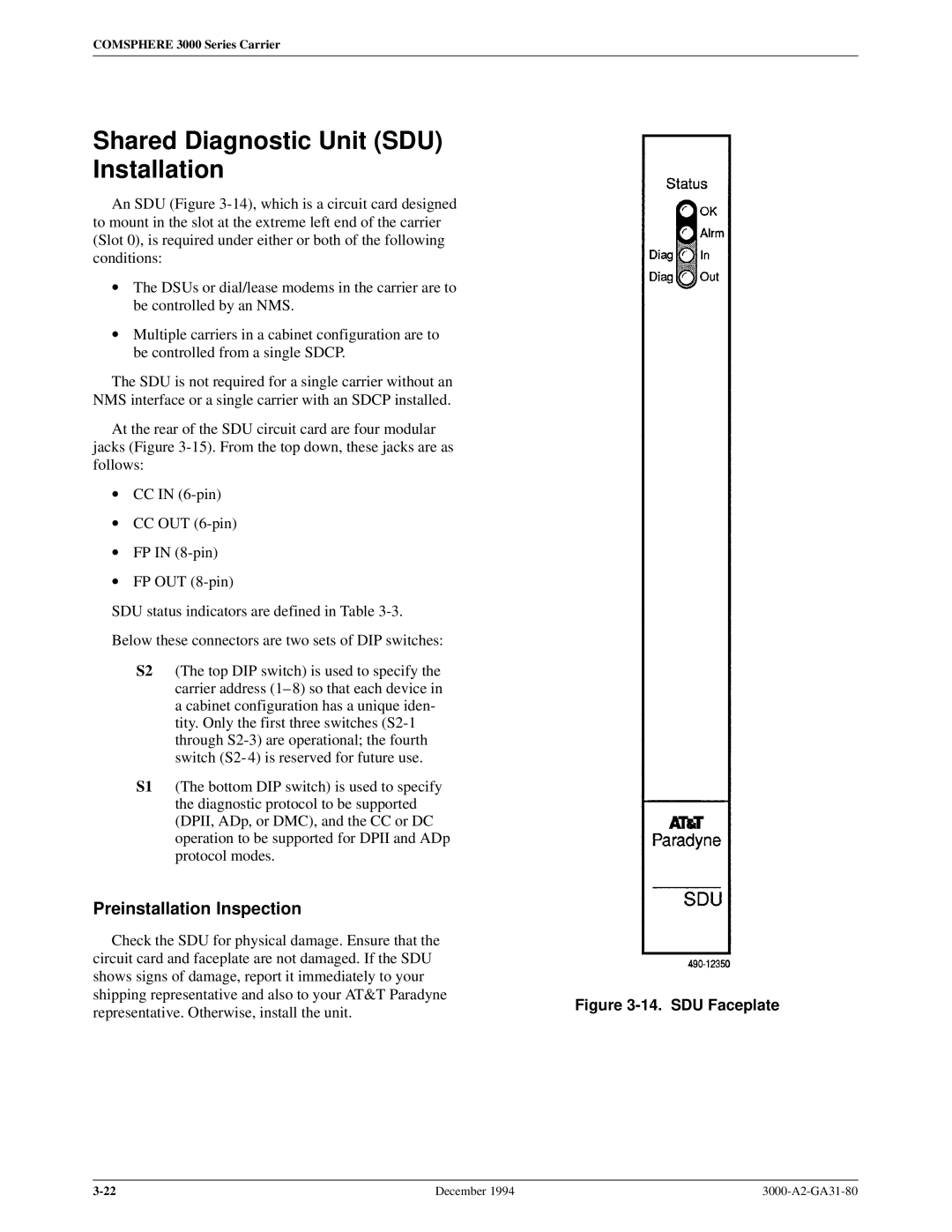
An SDU (Figure
• The DSUs or dial/lease modems in the carrier are to be controlled by an NMS.
• Multiple carriers in a cabinet configuration are to be controlled from a single SDCP.
The SDU is not required for a single carrier without an
NMS interface or a single carrier with an SDCP installed.
At the rear of the SDU circuit card are four modular
jacks (Figure
• CC IN
• CC OUT
• FP IN
• FP OUT
SDU status indicators are defined in Table
Below these connectors are two sets of DIP switches:
S2 (The top DIP switch) is used to specify the carrier address (1± 8) so that each device in a cabinet configuration has a unique iden- tity. Only the first three switches
S1 (The bottom DIP switch) is used to specify the diagnostic protocol to be supported (DPII, ADp, or DMC), and the CC or DC operation to be supported for DPII and ADp protocol modes.
Preinstallation Inspection
Check the SDU for physical damage. Ensure that the |
| |
circuit card and faceplate are not damaged. If the SDU |
| |
shows signs of damage, report it immediately to your |
| |
shipping representative and also to your AT&T Paradyne | Figure | |
representative. Otherwise, install the unit. | ||
|
December 1994 |