COMSPHERE 3000 Series Carrier
Auxiliary Backplane
Installation
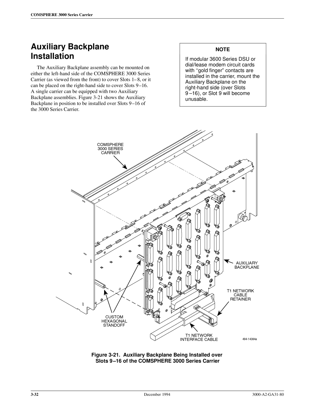
The Auxiliary Backplane assembly can be mounted on either the
A single carrier can be equipped with two Auxiliary Backplane assemblies. Figure
NOTE
If modular 3600 Series DSU or dial/lease modem circuit cards with ``gold fingerº contacts are installed in the carrier, mount the Auxiliary Backplane on the
9 ±16), or Slot 9 will become unusable.
Figure 3-21. Auxiliary Backplane Being Installed over Slots 9±16 of the COMSPHERE 3000 Series Carrier
December 1994 |