Installation
Network Interface Installation
Once the power transformer (and optional fan module and/or SDCP) has been installed, go to the rear of the cabinet to install the two
56 kbps digital service.
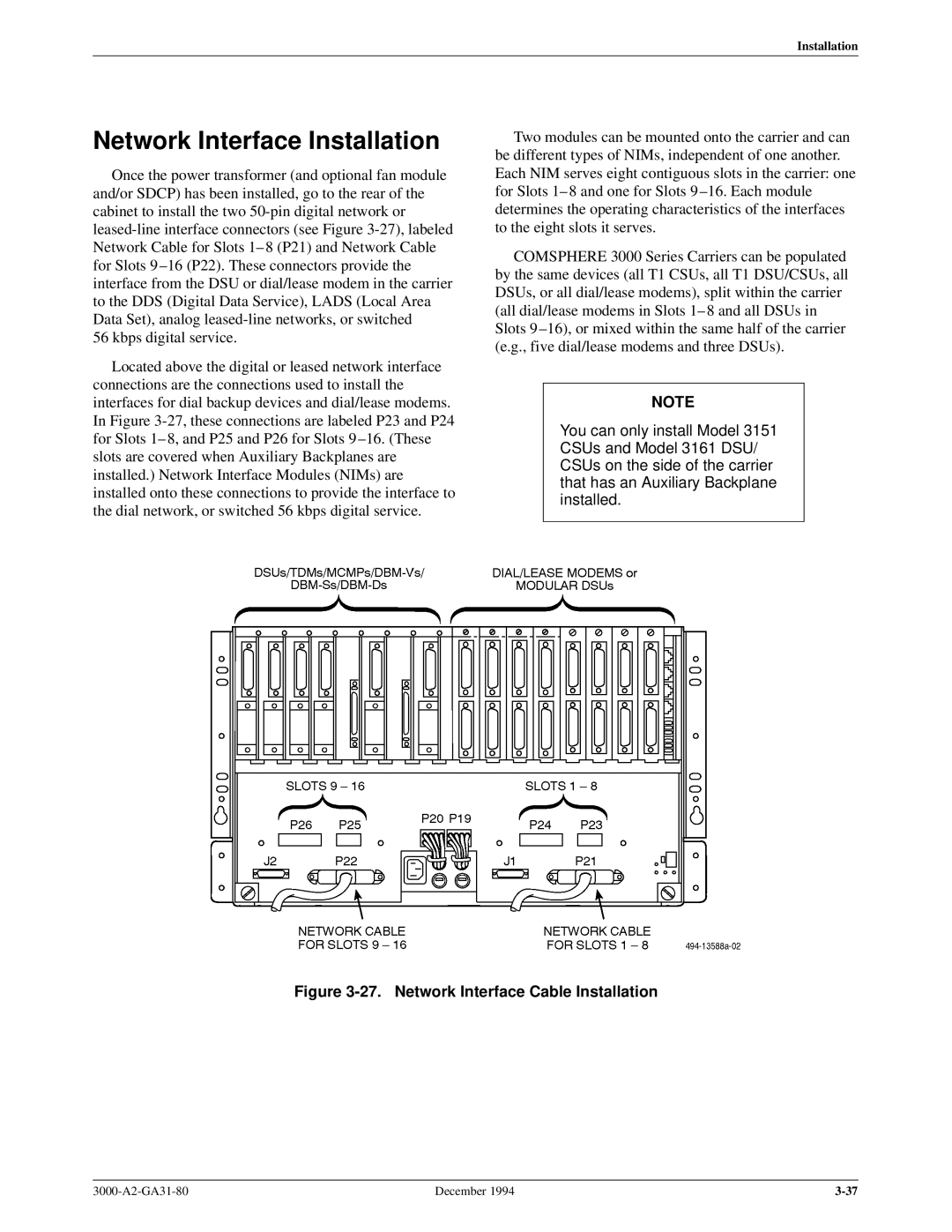
Located above the digital or leased network interface connections are the connections used to install the interfaces for dial backup devices and dial/lease modems. In Figure
Two modules can be mounted onto the carrier and can be different types of NIMs, independent of one another. Each NIM serves eight contiguous slots in the carrier: one for Slots 1± 8 and one for Slots 9 ±16. Each module determines the operating characteristics of the interfaces to the eight slots it serves.
COMSPHERE 3000 Series Carriers can be populated by the same devices (all T1 CSUs, all T1 DSU/CSUs, all DSUs, or all dial/lease modems), split within the carrier (all dial/lease modems in Slots 1± 8 and all DSUs in Slots 9 ±16), or mixed within the same half of the carrier (e.g., five dial/lease modems and three DSUs).
NOTE
You can only install Model 3151 CSUs and Model 3161 DSU/ CSUs on the side of the carrier that has an Auxiliary Backplane installed.
Figure 3-27. Network Interface Cable Installation
December 1994 |