COMSPHERE 3000 Series Carrier
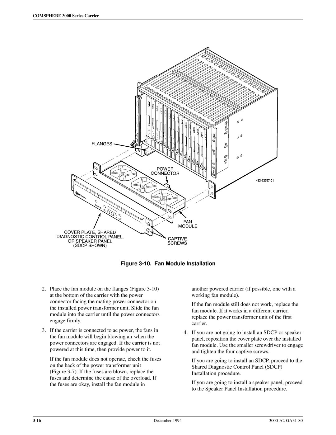
Figure 3-10. Fan Module Installation
2.Place the fan module on the flanges (Figure
3.If the carrier is connected to ac power, the fans in the fan module will begin blowing air when the power connectors are engaged. If the carrier is not powered at this time, then provide power to it.
If the fan module does not operate, check the fuses on the back of the power transformer unit (Figure
another powered carrier (if possible, one with a working fan module).
If the fan module still does not work, replace the fan module. If it works in a different carrier, replace the power transformer unit of the first carrier.
4.If you are not going to install an SDCP or speaker panel, reposition the cover plate over the installed fan module. Use the smaller screwdriver to engage and tighten the four captive screws.
If you are going to install an SDCP, proceed to the Shared Diagnostic Control Panel (SDCP) Installation procedure.
If you are going to install a speaker panel, proceed to the Speaker Panel Installation procedure.
December 1994 |
