COMSPHERE Interface Connections
|
| Table |
| Connectors on the COMSPHERE 3000 Series Carrier's Backplane | |
|
|
|
Connectors |
| Function |
|
|
|
P19, P20 |
| These connectors supply low voltage ac or low voltage dc from the power supply |
|
| unit onto the COMSPHERE 3000 Series Carrier's backplane. |
|
|
|
P21 |
| This |
|
| interface for DCEs (DSUs and dial/lease modems) in Slots 1 through 8. |
|
|
|
P22 |
| This |
|
| interface for DCEs (DSUs and dial/lease modems) in Slots 9 through 16. |
|
|
|
P23, P24 |
| These connectors are used by the Network Interface Modules (NIMs) to provide |
|
| the dial interface through a |
|
| through 8. |
|
|
|
P25, P26 |
| These connectors are used by the Network Interface Modules (NIMs) to provide |
|
| the dial interface through a |
|
| through 16. |
|
|
|
J1 |
| This |
|
| for dial/lease modems in Slots 1 through 8. |
|
|
|
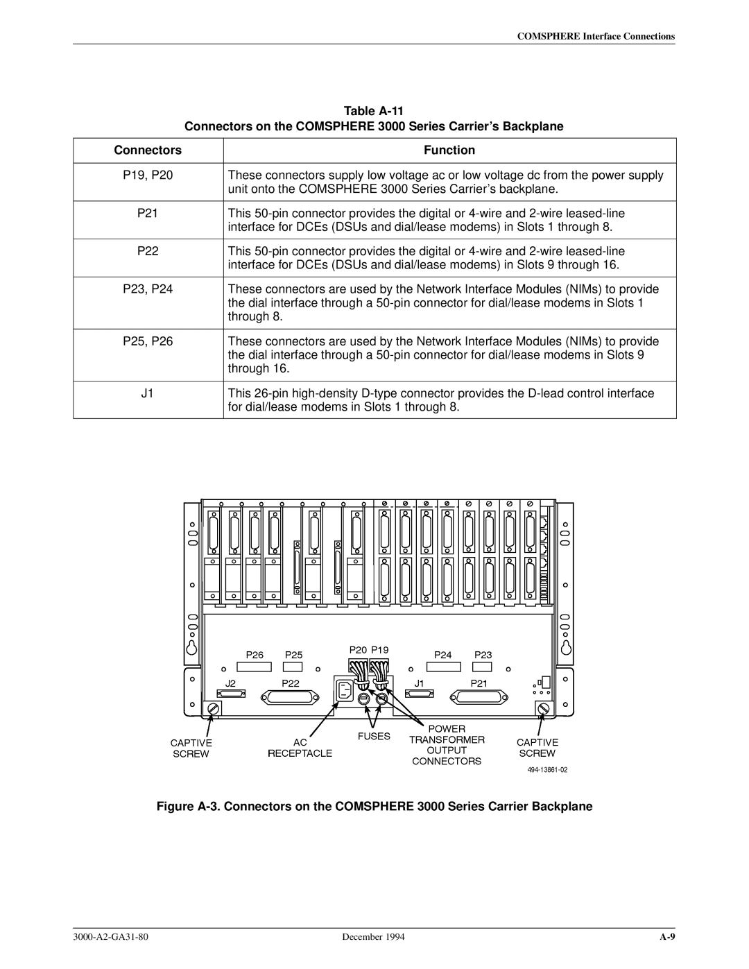
Figure A-3. Connectors on the COMSPHERE 3000 Series Carrier Backplane
December 1994 |