Paradyne 3000 manual Procedure

Models: 3000

1 131
Download 131 pages 24.91 Kb
Page 73
Image 73

COMSPHERE 3000 Series Carrier

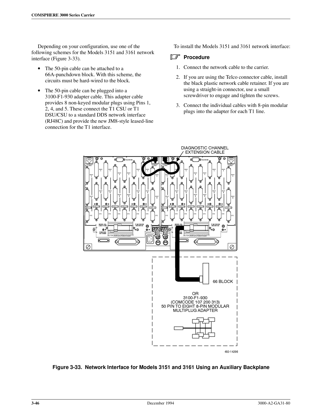
Depending on your configuration, use one of the following schemes for the Models 3151 and 3161 network interface (Figure 3-33).

The 50-pin cable can be attached to a

66A-punchdown block. With this scheme, the circuits must be hard-wired to the block.

The 50-pin cable can be plugged into a

3100-F1-930 adapter cable. This adapter cable provides 8 non-keyed modular plugs using Pins 1, 2, 4, and 5. These connect the T1 CSU or T1 DSU/CSU to a standard DDS network interface (RJ48C) and provide the new JM8-style leased-line connection for the T1 interface.

To install the Models 3151 and 3161 network interface:

.Procedure

1.Connect the network cable to the carrier.

2.If you are using the Telco connector cable, install the black plastic network cable retainer. If you are using a straight-in connector, use a small screwdriver to engage and tighten the screws.

3.Connect the individual cables with 8-pin modular plugs into the adapter for each T1 line.

Figure 3-33. Network Interface for Models 3151 and 3161 Using an Auxiliary Backplane

3-46

December 1994

3000-A2-GA31-80

Page 73
Image 73
Paradyne 3000 manual Procedure