Installation
Circuit Card Installation
The COMSPHERE 3000 Series Carrier is now properly installed and ready to accept modular and/or non-modular T1 CSUs, T1 DSU/CSUs, DSUs, TDMs, MCMPs, DBM-Vs, DBM-Ss, DBM-Ds, and modems.
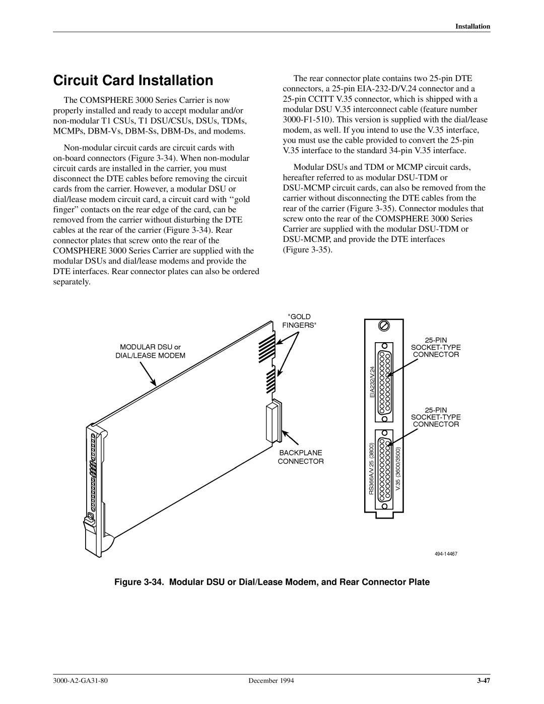
Non-modular circuit cards are circuit cards with on-board connectors (Figure 3-34). When non-modular circuit cards are installed in the carrier, you must disconnect the DTE cables before removing the circuit cards from the carrier. However, a modular DSU or dial/lease modem circuit card, a circuit card with ``gold fingerº contacts on the rear edge of the card, can be removed from the carrier without disturbing the DTE cables at the rear of the carrier (Figure 3-34). Rear connector plates that screw onto the rear of the COMSPHERE 3000 Series Carrier are supplied with the modular DSUs and dial/lease modems and provide the DTE interfaces. Rear connector plates can also be ordered separately.
The rear connector plate contains two 25-pin DTE connectors, a 25-pin EIA-232-D/V.24 connector and a
25-pin CCITT V.35 connector, which is shipped with a modular DSU V.35 interconnect cable (feature number 3000-F1-510). This version is supplied with the dial/lease modem, as well. If you intend to use the V.35 interface, you must use the cable provided to convert the 25-pin V.35 interface to the standard 34-pin V.35 interface.
Modular DSUs and TDM or MCMP circuit cards, hereafter referred to as modular DSU-TDM or DSU-MCMP circuit cards, can also be removed from the carrier without disconnecting the DTE cables from the rear of the carrier (Figure 3-35). Connector modules that screw onto the rear of the COMSPHERE 3000 Series Carrier are supplied with the modular DSU-TDM or DSU-MCMP, and provide the DTE interfaces
(Figure 3-35).
Figure 3-34. Modular DSU or Dial/Lease Modem, and Rear Connector Plate
3000-A2-GA31-80 | December 1994 | 3-47 |