Installation
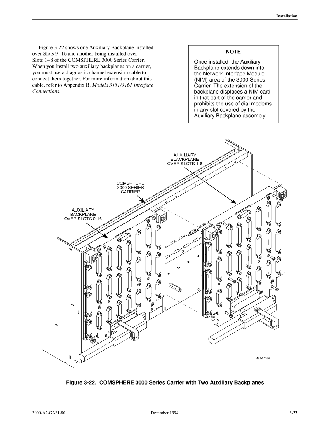
Figure 3-22 shows one Auxiliary Backplane installed over Slots 9 ±16 and another being installed over
Slots 1± 8 of the COMSPHERE 3000 Series Carrier. When you install two auxiliary backplanes on a carrier, you must use a diagnostic channel extension cable to connect them together. For more information about this cable, refer to Appendix B, Models 3151/3161 Interface Connections.
NOTE
Once installed, the Auxiliary Backplane extends down into the Network Interface Module (NIM) area of the 3000 Series Carrier. The extension of the backplane displaces a NIM card in that part of the carrier and prohibits the use of dial modems in any slot covered by the Auxiliary Backplane assembly.
Figure 3-22. COMSPHERE 3000 Series Carrier with Two Auxiliary Backplanes
December 1994 |