FR-S500
Electric Shock Prevention
This section is specifically about safety matters
Fire Prevention
Transportation and installation
Injury Prevention
Additional Instructions
Operation
Wiring
Trial run
Emergency stop
Maintenance, inspection and parts replacement
Disposing of the inverter
Treat as industrial waste
How to use the control circuit terminals
Standard connection diagram and terminal specifications
Main circuit terminals
Input terminals
Design information
Handling of the RS-485 connector
Connection to the Stand-Alone Option
Output terminal function parameters
Maintenance parameters 122
Current detection function parameters
Display function parameters
Errors Alarms 156
Parameter unit FR-PU04 setting 151
Troubleshooting 166
Calibration parameters 126
180
Specification list 170
Outline drawings 175
Chapter
Inverter
FR-S500
Standard connection diagram
Standard connection diagram and terminal specifications
Three-phase 200V power input Three-phase 400V power input
NFB MC
Main circuit
Single-phase 100V power input
Explanation of main circuit terminals
Control circuit
Alarm output
Symbol Terminal Name Definition
Signals
Indicator
Terminal block layout
1Three-phase 200V power input
Main circuit terminals
FR-S510WE-0.75K-NA
3Single-phase 100V power input FR-S510WE-0.1K, 0.2K, 0.4K-NA
FR-S520E-0.1K
Cables, wiring length, and crimping terminals
To 0.75K-NA FR-S520E 5K, 2.2K-NA 7K-NA
FR-S540E-0.4K
Wiring instructions
Selection of peripheral devices
NFB *1, 4 or
Select the NFB according to the inverter power
Supply capacity Install one NFB per inverter
To-ground leakage currents
Line-to-line leakage currents
∆n ≥ 10 × lg1+Ign+lg2+lgm
Path during commercial Power supply operation
Standard breaker
∆n ≥ 10 × lg1+lgn+3 × lg2+lgm
Main circuit terminals
Inverter input side magnetic contactor MC
Power-off and magnetic contactor MC
Handling of output side magnetic contactor
Inverter Start/Stop Circuit Example
NFB FR-BAL-H
General countermeasures
Regarding noise and the installation of a noise filter
BSF01
FR-BIF
Grounding precautions
Power supply harmonics
Suppressing the surge voltage on the inverter side
Inverter-driven 400V class motor
Rectifying the motor insulation
Bar Terminal Model Wire Size mm2
How to use the control circuit terminals
With Insulation Without Insulation Sleeve
Terminal Screw Size
RUN 24VDC
Changing the control logic
STF STR
RUN
STR R
Two-wire type connection is shown on the right
Two-wire type connection STF, STR
Input terminals
Run start and stop STF, STR, Stop
DC Injection Brake and Coasting to Stop Functionality
Three-wire type connection STF, STR, Stop
Forward-Reverse Rotation Switch-Over Timing Chart
Start/Stop Timing Chart for two-wire type
STF-SD
STR-SD
Voltage input 10, 2
External frequency selection REX, RH, RM, RL
Manual-Automatic Switching
Current input 4, 5, AU
AU-SD
Multi-Speed Operation Connection Example
Multi-Speed Setting
Frequency of 90Hz, set 90Hz in Pr . Factory setting 50Hz
Indicator connection and adjustment AM
Refer to page 126 for the procedure of indicator adjustment
Terminal AM Output Circuit
Control circuit common terminals SD, 5, SE
Signal inputs by contactless switches
Remote setting RL, RM, RH signals
Multi-speed setting RL, RM, RH, REX signals
Second function selection RT signal Pr to Pr setting
Current input selection AU signal Pr to Pr setting
Output shut-off MRS signal Pr to Pr setting
Start self-holding selection Stop signal Pr to Pr
Jog operation using external signals
External thermal relay input Pr to Pr setting
Jog operation JOG signal Pr to Pr setting
STF STR-SD
Related parameters
PID control valid terminal Pr to Pr setting
PU operation/external operation switchover Pr to Pr
Connection of the brake unit BU type
Connection to the Stand-Alone Option
Connection of the high power factor converter FR-HC
NFB MC1
Connection of the power regeneration common converter FR-CV
Connection of the parameter unit FR-PU04
Handling of the RS-485 connector
Product Model Maker
Wiring of RS-485 communication
Model
Maker
Product Model
Wiring of one RS-485 computer and one inverter
Wiring methods
Design information
Switchover
MC1
MC2
Memo
120
101
122
126
Function Parameter list
Indica Name Setting
Factory
Cus
Setting To
Func- Para- Indica Name Setting Range
Factory Refer
Tion meter tion
Tion
Func Para Indica Name Setting Range
Func- Para- Indica- tion meter tion
Name Setting Range
Remote Setting function
OHT, OLT, PE, OPT
THM, THT, BE, GF
PWM
Name Setting Range Minimum Factory
PID
Additional parameters
Maintenance parameters
Parameter for manufacturer setting
Calibration parameters
Indi Name Setting Range
Func
ECL
Communication Parameters
Indica Name Setting Range
Ter Tion
Func Parame- Indica Name Setting Range
Is valid
List of parameters classified by purpose of use
List of parameters classified by purpose of use
Explanation of functions parameters
Setting
Torque boost Pr
Increase this value for use when
Maximum and minimum frequency Pr
Name Factory Setting Setting Range
Base frequency, base frequency voltage Pr.3 , Pr.19 , Pr.47
Used to adjust the inverter
Motor rating Outputs voltage, frequency to
Name Factory
Multi-speed operation Pr , Pr , Pr Pr to Pr , Pr to Pr
Name Factory Setting Remarks Range
Acceleration/deceleration time Pr , Pr , Pr , Pr , Pr
Acceleration 120 Deceleration time s
Pr.3
Para Name Factory
Use an external thermal relay
Function Relay Function Applied Additional
H7 setting
Install a mechanical brake. No holding torque is provided
Can be adjusted according to the load
DC injection brake Pr , Pr , Pr
Changed to 4%
Starting frequency Pr
Load pattern selection Pr
Remarks Setting Range
RUN key rotation direction selection Pr.17
Using the FWD or REV
Jog operation Pr.15 , Pr.16
Stall prevention function and current limit function Pr
Explanation of functions parameters
Stall prevention Pr , Pr , Pr
To Refer to to
Function Description
Acceleration/deceleration pattern Pr
Set the acceleration/deceleration pattern
Frequency jump Pr To Pr
Extended function display selection Pr
Speed display Pr
Parameter Name Factory Setting
Mode indication
How to change the highest frequency
Flicker ... Parameter setting complete
Confirm the RUN indication and operation
Setting mode Turn To show
Press the Mode to choose the parameter
For the Pr setting method, refer to Press the SET To show
Gain and bias frequency settings are too close
Press the SET to set the value
Setting mode Turn To show Pr must be set to
Turn the to read another parameter Press
To return to
Up-to-frequency Pr
Start-time ground fault detection selection Pr
Output terminal function parameters
Output frequency detection Pr , Pr
On OFF
Current detection function parameters
Parameter
When the inverters output current falls
Zero current detection Pr , Pr
Monitor display Pr , Pr
Display function parameters
Setting dial function selection Pr
Parameter Name Factory Setting Remarks Range
Restart setting Pr , Pr , H6
Restart operation parameters
Monitoring reference Pr , Pr
Stfstr
Refer to the following table and set the parameters
Retry reset ⇒ Pr.66 to Pr.69 retry function Refer to
Additional function parameters
Remote setting function selection Pr
Function E2PROM
Pr Setting
Frequency setting storage conditions
Input terminal function selection Pr , Pr , Pr , Pr
Terminal function selection parameters
MRS
Setting Signal Functions Related Parameters Name
REX
JOG
Output terminal function selection Pr , Pr
Setting Signal Function Operation
FDN
FUP
Alarm Signal Output
Protective Functions Major Faults for Retries
Operation selection function parameters
Retry function Pr , Pr , Pr , Pr
102
Pr.72 Setting Description
Pr.70 Setting Description
PWM carrier frequency Pr , Pr
You can change the motor sound
Voltage input selection Pr
Reset Selection PU Stop Selection Setting
Reset selection/PU stop selection Pr
Input filter time constant Pr
From the operation panel PU
STR OFF
Cooling fan operation selection Pr
Pr Setting Function
Parameter write disable selection Pr
Reverse rotation prevention selection Pr
Operation mode selection Pr
Function LED Indication
Operation Running frequency Start Mode Signal
EXT
STF, STR
PU operation interlock
MRS Signal Function/Operation
Preparation
Operating Condition
To Refer to to
Operation mode switching by external signal
X16 Signal Operation Mode
PID control Pr to Pr
Setting Basic PID control configuration
PID action overview
Operation example for stepped changes of measured value
PID action
PD action
Both actions for control
Reverse action
Contact input signal AU Signal need not be turned on
Wiring example
Forward action
Pr =
Entry Description
O signals
Parameter setting
Adjustment procedure
END
Calibration example
Start
Detector output calibration
Set point input calibration
Slip compensation Pr , Pr , Pr
Auxiliary parameters
Rated slip =
×100%
Operating conditions
Setting Description
Automatic torque boost selection Pr
Maintenance output function H1 , H2
Maintenance parameters
Name Factory Setting Remarks Range
Motor primary resistance Pr
PLC
Current average value monitor signal H3 , H4 , H5
Pulse operation
Output pulse of the Y93 signal is shown below
Setting
72000h
40000h
Meter frequency meter calibration C1
Parameter Name Factory Setting Setting Range Remarks
Calibration parameters
Flicker ... Parameter setting complete
To Refer to ,
Clear the alarm history
Alarm history clear ECL
Clear parameters
Parameter clear CLr
Operational functions
Symbol Switching Type Switching Method
Communication parameters
Location PU operation External Computer link
Operation mode-based functions
Remarks Reflection Setting Range
Communication settings n1 to n7 , n11
Communication-related parameters
Computer
133
Ing
Computer programming Communication protocol
Operation Run
Reply data from inverter to computer during data read
Data format
Reply data from inverter to computer during data write
Data definitions
Response time
Waiting time
Example When communication parameter n6= 0.1 to
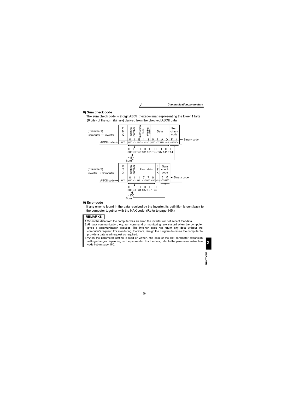
Sum check code
Error code
140
Data Description
Setting items and set data
H7A
HFA
H6E
H6D
E2PROM
HED
Data
Commu Calibra Other
Nication
Communication error
Error Code List
Operation at alarm occurrence
Program example
General flowchart
On COM1GOSUB*REC
If LOC1=0 then Return Printreceive Data
External Remarks Location N9 Pr speed
Operation and speed command source n8 , n9
N8 Pr operation Command source
N9 Pr speed Command source
Link startup mode selection n10
Explanation of table
External
149
15.4 E2PROM write selection n12
N13 Setting Display Language
Parameter unit FR-PU04 setting
PU display language selection n13
PU buzzer control n14
PU main display screen data selection n16
PU contrast adjustment n15
100
During stop During operation
N17 Setting Disconnected PU Detection PU Setting Lock
Disconnected PU detection/PU setting lock selection n17
Monitor display and the Resetstop are valid
154
This chapter explains the protective functions of this
Protective Functions
Errors Alarms
Major failures
Error alarm definitions
OC During Acc
Stedy Spd OC
OV During Dec
OV During Acc
Stedy Spd OV
Motor Overload
Br. Cct. Fault
Inv. Overload
Sink O/Temp
Is set to OH
Minor failures
CPU Fault
PU Leave Out
Retry No Over
Check point
FR-PU04
Write errors
Correspondence between digital and actual characters
Resetting the inverter
Pr . Refer to page 36
Actual Display
Motor remains stopped
Troubleshooting
Motor current is large
Operation mode is not changed properly
Specification list 170 Outline drawings 175
Specifications
Three-phase 200V power supply
Specification list Ratings
Three-phase 400V power supply
Single-phase 100V power supply
Common specifications
Maximum and minimum frequency settings, frequency jump
Unit mm inches
Outline drawings
Φ5 hole 118 128 Cooling fan×1
177
178
Appendix
Appendix 1 Parameter Instruction Code List 180
Appendix 1 Parameter Instruction Code List
Tion Number Read
Setting Instruction
Name Code Link Data
Operation panel display
Multi-speed setting 01Hz Speed
C4903 Voltage bias frequency 6C/EC=0 Voltage gain
Source
Revisions