DJM-3000
DRB1315 En/Fr/Ge/It/Du/Sp
English Français Deutsch Español Nederlands Italiano
Contents
Table DES Matieres
Checking Accessories
Features
Verifier LES Accessoires
Caracteristiques
Cleaning the Unit
Installing the DJM-3000 in an EIA rack
Emplacement
Installation du DJM-3000 dans une baie EIA
Cassette deck, etc Player
Power cord from the outlet Raccordements
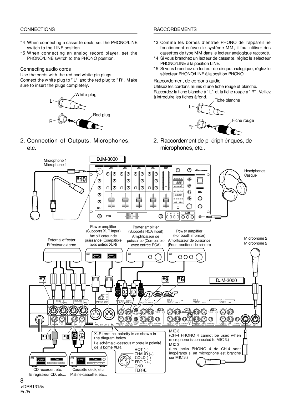
Connections Raccordements
Connection of Outputs, Microphones, etc
Raccordement de périphériques, de microphones, etc
Connections
Raccordements
Digital OUT
Master Level ATT
REC OUT
Control Panel Pupitre de commande
¥ MIC Microphone Controls ¥ MIC Commandes de microphone
CH-1 à CH-4 Commandes d’entrée de canal
Part Names and Functions Noms ET Fonctions DES Organes
Master Commandes principales
Part Names and Functions
CH-1 to CH-4 Channel Input Controls
Master Master Controls
Booth Monitor Control
Power Switch Headphones Controls
Commande Booth Monitor Moniteur de cabine
Interrupteur général Power Commandes Headphones casque
\ Fader Start Switches CH-1, CH-2, CH-3, CH-4
« Commandes Beat Effects effets de mesure
« Beat Effects Controls
§ Auto BPM Counter
≠ Effect beat selector switches @, #
Parameter 1 Parameter 1 / BPM counter
Parameter 1 Paramètre 1 / Compteur BPM
≠ Sélecteurs de mesure avec effet @, #
‹ Time Parameter
Commandes Effect MIX mixage d’effet
Effect MIX Controls
Using the Effect Functions
Features of Various Effectors
Utiliser LES Fonctions Effet
Caractéristiques des divers effecteurs
Utiliser LES Fonctions Effet
Reverb
Filter
Flanger
Items Set for Each Effect
Eléments réglés pour chaque effet
Réglez la valeur du paramètre
Using the Effect Functions Utiliser LES Fonctions Effet
Set the parameter value
BPM
Turn on the Effect ON/OFF switch
Actionnez l’interrupteur d’effet ON/OFF
Using the Effect Functionsutiliser LES Fonctions Effet
Effector Settings
Operating Reverb and Pitch Shifter
Opérations réverbération et changement de hauteur de son
Turn the Effect ON/OFF switch on
Mettez l’interrupteur d’effet ON/OFF sur la position on
Using an External Effector
Utilisation d’un effecteur externe
Using the Auto Mode to Count BPM
Utilisation du Mode Auto pour compter la valeur BPM
BPM Counting Comptage DE BPM
÷ La LED 2 de l’affichage du paramètre effet/BPM s’allume
Using the Manual Mode to Count BPM
Utilisation du Mode Manuel pour compter la valeur BPM
BPM Counting
Comptage DE BPM
Counter BPM counter range selector switch
Effect displays parameter BPM display
De compteur BPM
Affichages de
Using the Fader Start Function
Cross Fader Start Play and Back Cue Play
Control cords Cordons de commande
CMX-3000
DJM-3000
CMX-3000 CMX-5000 CDJ-1000 CDJ-100S CDJ-500S
Precaution
Starting with the Channel Fader
Démarrage par le variateur de canal
Utilisation DE LA Fonction DE Démarrage PAR Variateur
Starting with the Cross Fader
Démarrage par Fondu enchaîné
Actionnez le commutateur Fader Start CH-1
Raccordé
Using the Effect MIX Function
Effect Mix Features
Effect Mix Fader Mode
Mode Variateur à mixage d’effets
Effect Mix Auto Mode
Mode Mixage d’effet automatique
Example When set for 4-beats
Example When set for 4 beats
Selecting the Effect Mix Function
Sélection de la fonction de Mixage d’effets
Utilisation DE LA Fonction DE Mixage D’EFFETS
OFF
Cross Fader Assign
Assign a Fader Assign B
Fader
Effect Mix Fader Mode
Mode Variateur à mixage d’effet
Effect Mix Auto Mode
Mode Mixage d’effet automatique
Set the Effect MIX selector switch to Auto
Operate the Cross fader Lever
Réglez le sélecteur Effect MIX à la position Auto
Troubleshooting
Problem Possible Cause Countermeasure
LEVEL/DEPTH
DRB1315 En
Depannage
Problème Cause possible Remède
Specifications
Caracteristiques Techniques
Inhalt
Indice
Betriebsbedingungen
Condizioni ambientali di funzionamento
Caratteristiche
Verifica Degli Accessori
Merkmale
Vorsichtshinweise ZUR Handhabung
Avvertenze PER L’USO
Anschlüsse
Collegamenti
Anschlüsse an den Eingangsbuchsen
Collegamento dei dispositivi di ingresso
Anschlüsse
Anschließen der Audiokabel
Collegamenti
Collegamento di cavi audio
Anschlüsse Collegamenti
Digital OUT-Buchsen
Da CH-1 a CH-4 comandi degli ingressi dei canali
Bedienfeld Quadro di comando
Bereich CH-1 bis CH-4 Bedienelemente für Kanaleingänge
Master comandi master
Bezeichnungen UND Funktionen DER Bedienelemente
MASTER-Bereich Bedienelemente für Master-Ausgang
Booth Monitor Kabinen-Monitorregler
Booth Monitor
‘ Bedienelemente für Kreuz-Faderhebel
Comando del monitor all’interno della gabbia
« Comandi degli effetti di battuta Beat Effects
\ Fader START-Schalter CH-1, CH-2, CH-3, CH-4
« Beat EFFECTS-Bereich Bedienelemente für Beat-Effekte
Bis 4, MIC, Master Programmquellen-Anzeigen
Parameter 1 Effekt-Parameter-/BPM-Display
Beat Effekt-synchrone Anzeigen/Beat-Anzeigen
≠ Effekt-Beat-Wahlschalter @, #
Effect MIX-Bereich Bedienelemente für Effekt-Mischen
Comandi degli effetti di missaggio Effect MIX
Gebrauch DER Effektfunktionen
USO Delle Funzioni Degli Effetti
Merkmale der verschiedenen Effektfunktionen
Caratteristiche degli elaboratori di effetti
USO Delle Funzioni Degli Effetti
Filter filtro
Flanger flangia, bordo, bordone
Reverb riverbero
Pitch spostamento dell’altezza del suono
Einstellpunkte jedes Effekts
Parametri predisposti per ciascun effetto
Durata del ritardo Rapporto di missaggio dell’effetto
Scatti di millisecondi Ritardato
Stellen Sie jeden Parameter auf den gewünschten Wert ein
Predisporre il valore del parametro
Einstellen der Verzögerungszeit
Predisposizione della durata del ritardo
Schalten Sie den Effekt-Ein/Aus-Schalter ON/ OFF ein
Attivare l’interruttore ON/OFF dell’effetto
Scatti dell’1% Riverberato
Einstellungen für die Effekte Reverb und Pitch Shifter
Predisposizioni del generatore di effetti
Einstellen der Tonhöhenverschiebung
Predisposizione dell’entità dello spostamento
Verwendung eines externen Effektgerätes
Uso di un elaboratore di effetti esterno
Stellen Sie den Return-Pegel wunschgemäß ein
Regolare il livello del ritorno
Bringen Sie den Effekt-Wahlschalter in Stellung Auto BPM
Bestimmung DES BPM- Wertes
Conteggio Delle BPM
Uso della modalità manuale per il calcolo delle BPM
Bestimmung DES BPM-WERTES
Drücken Sie den H.P CUE-Schalter von CH-1
Conteggio Delle BPM
Effekt-Parameter-/ Anzeigen BPM-Display
Visualizzazione della BPM
Dell’effetto e
Della BPM
Funzione DI Avvio CON Dissolvenza
Steuerkabel Cavi di comando
Wiedergabestart über Kanal-Faderhebel
Avvio con dissolvenza da uno dei canali
Zur Beachtung
Precauzione
Wiedergabestart über Kreuz-Faderhebel
Avvio con dissolvenza incrociata
Predisporre sul lettore CD un punto di inizio e
Portare il lettore in modalità di attesa o di pausa
Effektmisch-Merkmale
Caratteristiche della funzione di missaggio degli effetti
Effektmisch-Fadermodus
Modalità di dissolvenza con missaggio degli effetti
Effektmisch-Automatikmodus
USO Della Funzione DI Missagio Degli Effetti
Modalità automatica di missaggio degli effetti
Beispiel Bei Einstellung auf 4 Beats
Wahl der Effektmisch-Funktion
Selezione della funzione di missaggio degli effetti
Illuminata
Lampeggia
Dal lato B
Seite a Hinzufügen von Effekten zum Blinkt
Dal lato a Applicando degli effetti al lato a
Effektmisch-Fadermodus
Modalità di dissolvenza con missaggio degli effetti
Effektmisch-Automatikmodus
Modalità automatica di missaggio degli effetti
Betätigen Sie den Kreuz-Faderhebel
Agire sul cursore della dissolvenza incrociata
Gestellten Effektzeit wird der Ton von a ausgegeben
Bringen Sie den Effect MIX-Wahlschalter in Stellung Auto
Portare il selettore Effect MIX sulla posizione Auto
DRB1315 Ge
Fehlerbeseitigung
Störung Mögliche Ursache Abhilfemaßnahme
Diagnostica
Problema Possibile causa Rimedio
Technische Daten
Dati Tecnici
Inhoudsopgave
Índice
Plaats van gebruik
Condiciones de Funcionamiento
Toebehoren Controleren
Comprobación DE LOS Accesorios
Eigenschappen
Características
Waarschuwingen I.V.M. HET Gebruik
Precauciones Para LA Manipulación
Aansluitingen
Conexiones
Aansluiten van apparatuur op de ingangen
Conexión del equipo de entrada
Aansluiten van uitgangsapparatuur, microfoons enz
Conexión de las tomas de salida, micrófonos, etc
Aansluitingen
Conexiones
Talk Over Level verzwakkingsregelaar
Geschikt voor microfoons met XLR of Phone type stekkers
Talk Over Level
Es compatible con micrófonos clavijas de los tipos XLR y
MIC 1 Toma de entrada del micrófono
Bedieningspaneel Panel de control
¥ MIC microfoonregelaars ¥ MIC Controles de micrófonos
Benaming EN Functie VAN DE Bedieningsorganen
Nombres DE Controles Y SUS Funciones
Booth Monitor regelaar
Power netschakelaar Headphones regelaars
Booth Monitor Control de monitor de la cabina
‘ Kruisfader-regelaars
« Beat Effects controles de efectos del tiempo
\ Fader Start schakelaars CH-1, CH-2, CH-3, CH-4
« Beat Effect regelaars
4, MIC, Master bronindicators
Beat synchrone effect-indicators/ritme-indicators
Parameter 1 Parameter 1/BPM-teller
≠ Effectritme-keuzeschakelaars @, #
FADER/OFF/AUTO selector de mezcla de efectos
Effect MIX regelaars
Effect MIX Controles de mezcla de efectos
Características de las diversas unidades de efectos
DE EFFECT-FUNCTIES Gebruiken
Eigenschappen van de verschillende effectors
DE EFFECT-FUNCTIES Gebruiken
Utilización DE LAS Funciones DE Efectos
Pitch desplazamiento del tono
Pitch Toonhoogte wijzigen
SND/RTN Invoer/uitvoer van extern effect
Ingestelde waarden voor elk effect
Elementos de ajuste para cada efecto
Stel de parameterwaarde
Ajuste el valor del parámetro
Ejemplo Aplicación del efecto de retardo a la música del CH
Instellen van de vertragingstijd
Zet de effect ON/OFF schakelaar aan
Conecte el interruptor ON/OFF de efectos
Nagalm en toonhoogtewijziging
Operaciones de reverberación y de desplazamiento del tono
Effectorinstellingen
Trappen van 1% Het weerkaatste geluid
Instellen van de toonhoogte
BPM-display Effectparameter
Ajuste del tono
Visualizador de
Gebruik van een externe effector
Empleo de una unidad de efectos externos
Stel de parameters enz. van de externe effector
Stel het retourniveau
BPM-WAARDE Meten
Medición DE BPM
BPM-WAARDE Meten
Druk op de CH-1 H.P CUE schakelaar
Medición DE BPM
Presione el interruptor H.P CUE del CH-1
Visualizadores del
Indicators voor
BPM-meetbereik
Gebruik VAN DE Faderstartfunctie
Gebruik VAN DE Faderstartfunctie CON Fundido
Bedieningssignaalsnoeren Cables de control
Via de kanaalfader starten
Inicio con fundido de canal
Schuif de kanaalfader-schuifregelaar helemaal naar beneden
Utilización DE LA Función DE Inicio CON Fundido
Via de kruisfader starten
Inicio con fundido transversal
Reproducción
Ejemplo Selector Assign a
Gebruik VAN DE EFFECT- Mengfunctie
Beschikbare effect-mengfuncties
Características de la mezcla de efectos
Effect-mengfaderfunctie
Automatische effect-mengfunctie
Utilización DE LA Función DE Mezcla DE Efectos
Modo automático de mezcla de efectos
Voorbeeld Bij een 4-maten instelling
Kiezen van de effect-mengfunctie
Selección de la función de mezcla de efectos
Licht OP UIT
Licht OP
Wanneer de functie wordt
Kant wordt weergegeven Wanneer effecten worden
Toegepast op de a kant Wanneer het geluid van de B
Toegepast op de B kant
Gebruik VAN DE EFFECT-MENGFUNCTIE Efectos
Effect-mengfaderfunctie
Modo de fundido de mezcla de efectos
Automatische effect-mengfunctie
Modo automático de mezcla de efectos
Bedien de kruisfader-schuifregelaar
Opere la palanca de fundido transversal
Is verstreken zal het a geluid worden weergegeven
Zet de Effect MIX keuzeschakelaar op Auto
Ajuste el selector Effect MIX en Auto
Zelf Storingen Verhelpen
Probleem Mogelijke oorzaak Maatregel
Depth
Solución DE Problemas
Problema Causa posible Solución
Technische Gegevens
Especificaciones
118
119
TSZRZ/01L00000