DJM-600
Information to User
DRB1252 En/Fr
Contents
Checking Accessories
Verifier LES Accessoires
Features
Caracteristiques
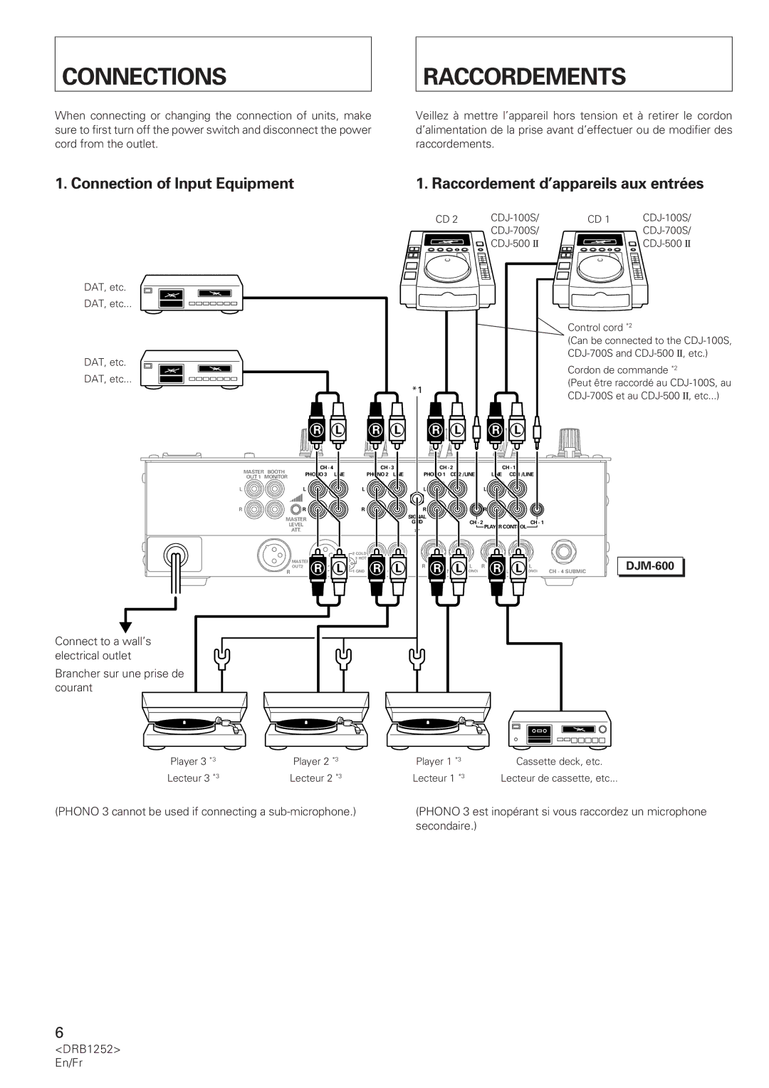
Connection of Input Equipment
Phono 3 cannot be used if connecting a sub-microphone
Connections Raccordements
Secondaire DRB1252 En/Fr
Connections
Connection of Outputs, Microphones, etc
Microphones, etc
Raccordements
REC OUT
Connections Raccordements
Master Level ATT
REC OUT Sortie REC
Control Panel Tableau de bord
Part Names
Functions
Main Microphone Input Terminal and Microphone Control Knob
Part Names and Functions
Talk Over
Noms ET Fonctions DES Elements
Cross Fader Assign a Cross Fader Assign B
~ Cross Fader Curve
$ Affichage BPM voir
$ BPM Display see
Effect Parameter and BPM Display see
Paramètre effet et affichage BPM voir
ON/OFF, TAP Effect/Sampler ON/OFF Switch and Tap Switch
Effect/Sampler Selector Switch
CH. Select Effect/Sampler Channel Selector Switch
Parameter 1, 2 Effect/Sampler Parameter 1 and 2 Knobs
Features of Various Effectors
Caractéristiques des divers effecteurs
Utiliser LES Fonctions EFFET/ECHANTILLONNAGE
Filter
Flanger
Reverb
Sampler REC
Sampler Play
Measuring BPM
Mesurer la valeur BPM
Auto BPM
Appuyez sur le sélecteur CH-1 du compteur BPM
÷ Display when the BPM of CH-1 and CH-2 126 match
Press auto BPM counter selector CH-1
÷ Le voyant LED 1 s’allume sur l’affichage BPM
Measuring BPM in Manual Mode
Mesurer la valeur BPM en mode manuel
When BPM cannot be measured in auto BPM mode
Items Set for Each Effect
Eléments réglés pour chaque effet
Réglez la valeur du paramètre
Delay
Set the parameter value
Utiliser LES Fonctions EFFET/ECHANTILLONNAGE
Precautions
Turn on the effect/sampler ON/OFF switch
Setting to Balance Original and Delayed Sound Levels
Actionnez l’interrupteur effet/échantillonnage
Opérations réverbération et changement de ton
Effector Settings
Operating Reverb and Pitch Shifter
Réglages de l’effecteur
OFF
Turn the effect/sampler ON/OFF switch on and then off again
÷ Display when CH-3 has been pitch-shifted by 90%
Effet/échantillonnage alors que les effets retard, écho et
Return
Using an External Effector
Utiliser un effecteur externe
SEND/RETURN
Using Sampler Recording
Utiliser la fonction Enregistrement par l’échantillonneur
Sampler REC
Affichage du rythme
Stretch Loop Play
Using Sampler Playback Functions
Utiliser les fonctions Lecture échantillonneur
Set the playback time and playback level
Using Sampler Edit Function
Using the Fader Start Function
CDJ-100S DJM-600
Starting with the Channel Fader
Démarrage par le variateur de canal
Utiliser LA Fonction Demarrage PAR Variateur
Démarrage par le variateur de son
Assign a switch
Starting with the Cross Fader
Commutateur Assign a
Troubleshooting
Problem Possible Cause Countermeasure
Depannage
Problème Cause possible Remède
÷ Déconnectez le microphone secondaire
Audio Section
Specifications
Accessories
Electrical Section, etc
Section audio
Accessoires
Caracteristiques Techniques
Section électricité, etc
Vorsicht MIT DEM Netzkabel
Inhalt
Indice
Precauzioni
Accessori
Aufstellung UND Reinigung
Prüfung DES Zubehörs
Funktionen
Caratteristiche
Anschlüsse Collegamenti
Geräte an Eingänge anschließen
Anschluß an Netzsteckdose Collegare alla tensione di rete
Collegamenti
Anschlüsse
Audiokabel anschließen
Collegamento dei cavi audio
Anschlüsse Collegamenti
Plus + HOT +
Bedienelemente UND Funktionen Nomi Delle Parti E Funzioni
Bedienfeld
Bedienelemente UND Funktionen
Nomi Delle Parti E Funzioni
Cross Fader Assign A, Cross Fader Assign B
@ Master Balance
$ BPM-Anzeige siehe Seite
# Booth MONITOR-Pegelregler
# Manopola del livello Booth Monitor
Effekt-Parameter und BPM-Anzeige siehe Seite
Parameter 1, 2 Effekt/Sampler-Regler für Parameter 1 und
Effekt/Sampler-Wahlschalter
CH. Select Effekt/Sampler-Kanal-Wahlschalter
Selettore del canale Effect/Sampler
Beat Effector Effekte, die mit BPM verknüpft sind
Merkmale der verschiedenen Effectoren
Caratteristiche dei processori di effetti
Processore di effetti BPM effetti collegati ai BPM
Echo wiederholte Sounds
Verwendung DER EFFEKT/SAMPLER-FUNKTIONEN
Utilizzo Delle Funzioni EFFECT/SAMPLER
Mitte
SEND/RETURN Ein-/Ausgang für externe Effektgeräte
SEND/RETURN ingresso/uscita effetto esterno
Riproduzione del suono campionato a 4 battiti
BPM-Messung
Misurazione BPM
Zähler
Drücken Sie CH-1 auf dem Auto BPM counter selector
Premere il selettore CH-1 del contatore automatico BPM
BPM-Meßbereichs Wahlschalter
Gemessen werden können
BPM-Werte im manuellen Modus messen
Misurazione dei BPM in modalità manuale
Misurazione BPM Contatore
Einstellungsbereich des jeweiligen Effekts
Delay, Echo, Auto Pan, Auto Trans, Filter und Flanger
Step da 1 msec Delay
Impostazione dei parametri per ogni effetto
Stellen Sie den Parameterwert ein
Stellen Sie den Effekt/Sampler-Wahlschalter auf
Stellen Sie den Effekt/Sampler-Kanal-Wahlschalter auf
Impostare il valore del parametro
Vorkehrungen
Schalten Sie den Effekt/Sampler-ON/OFF-Schalter ein
Attivare l‘interruttore ON/OFF di Effect/Sampler
Precauzioni
Effector-Einstellungen
Reverb und Pitch Shifter bedienen
Utilizzo di Reverb e Pitch Shifter
Impostazioni processore di effetti
Display dei battiti
Beat-Anzeige
Effekt-Beat Wahlschalter
Selettore battiti dell‘effetto
Einen externen Effector verwenden
Utilizzo di un processore di effetti esterno
Stellen Sie die Aufnahmezeit ein
Sampler-Aufnahme verwenden
Registrazione da campionatore
Impostare il selettore Effect/Sampler su Sampler REC
Selettore dei battiti dell‘effetto
Stellen Sie die Wiedergabezeit und den Wiedergabepegel ein
Sampler-Wiedergabefunktionen verwenden
Utilizzo delle funzioni di riproduzione del campionatore
Impostare il tempo ed il livello di riproduzione
Sampler-Edit-Funktionen verwenden
Utilizzo della funzione Edit del campionatore
START-FUNKTION Fader Start
Fader-Wiedergabestart für angeschlossene CD-Player
Quando viene avviato un lettore CD collegato
Verwendung DER Fader START-FUNKTION
Player mit Kanal-Fader starten
Avvio con Channel Fader
Riproduzione con Cross Fader e ritorno al cue point
Avvio con Cross Fader
Interruttore Assign a Controllo del volume Cross Fader
Mit Cross-Fader starten
Schalter Assign a Cross-Fader-Lautstärkeregler
Problem Mögliche Ursache Beseitigung
Fehlerbeseitigung
Risoluzione DEI Problemi
Problema Possibile causa Possibile soluzione
Elektrische Daten usw
Technische Daten
Audiodaten
Zubehör
Sezione audio
Accessori
Specifiche
Sezione elettrica, ecc
Waarschuwing Netsnoer
DRB1252 Du/Sp
Inhoudsopgave
Toebehoren Controleren
Waarschuwingen I.V.M. HET Gebruik
Advertencias DE Funcionamiento
Comprobación DE LOS Accesorios
Eigenschappen
Características
Aansluitingen Conexiones
Aansluiting van toestellen op de ingang
Aansluiten op het stopcontact
Aansluiting van de audiokabels
Aansluiting op uitgangen, microfoons, enz
Aansluitingen
Conexiones
Aansluitingen Conexiones
REC OUT salida de grabación
Koud
Namen EN Functies VAN
Onderdelen Funciones
Bedieningspaneel Panel de control
Nombres DE Piezas Y Funciones
Kruisfadervolume
Kanaalvolume
Hoofdvolume
# Booth MONITOR-niveauregelaar
$ Pantalla de BPM véase la página
$ BPM-Display zie pagina
Effectparameter- en BPM-display zie pagina
Pantalla de parámetros de efectos y BPM véase la página
Parameter 1, 2 Effect/Sampler-parameter 1 en 2 knoppen
Effect/sampler-kanaalkeuzeschakelaar
CH. Select Effect/Sampler- kanaalkeuzeschakelaar
Selector de efecto/muestreador
Eigenschappen van de verschillende effectors
Características de los distintos generadores de efectos
DE EFFECT/SAMPLER-FUNCTIES Gebruiken
Utilización DE LAS Funciones DE EFECTO/MUESTREADOR
Utilización DE LAS Funciones DE EFECTO/MUESTREADOR Filter
Pitch Toonhoogte wijzigen
SEND/RETURN Invoer/uitvoer van extern effect
Pitch cambiador de afinación
Bucle de estiramiento
Continu afspelen met uitrekken/inkrimpen
Continu afspelen
Bucle
Stel de effect/sampler-keuzeschakelaar in op
BPM meten
Medición de BPM
Stel de effect/sampler-kanaalkeuzeschakelaar in op
Druk op de keuzeschakelaar CH-1 van de BPM- teller
÷ Pantalla cuando coinciden los BPM del CH-1 y del CH-2
Wanneer de BPM-waarde niet automatisch kan worden gemeten
BPM handmatig meten
Medición de los BPM en modo manual
Cuando no es posible medir los BPM en modo automático
Ingestelde waarden voor elk effect
Elementos de cada efecto
Fije el valor del parámetro
Stel de parameterwaarde
Ponga el selector de efecto/muestreador en
De vertragingstijd instellen
Opgelet
Zet de effect/sampler-aan-uit-schakelaar op on
Encienda el interruptor ON/OFF del efecto/ muestreador
Precauciones
Effectorinstellingen
Nagalm en toonhoogtewijziging
Funcionamiento de la reverberación y el cambiador de tonos
Ajustes del generador de efectos
Ritmedisplay
90%
LED Controlelampje
Keuzeschakelaar voor het effectritme
De externe effector gebruiken
Utilización de un generador de efectos externo
Stel de effect/sampler- keuzeschakelaar in op
Sampler-opname
Utilización de la grabación del muestreador
Stel de opnameduur
100
Selector de batido de efecto
De weergavefuncties van de sampler gebruiken
Stel de afspeelduur en het afspeelniveau
Ajuste el tiempo y el nivel de reproducción
De EDIT-functie van de sampler gebruiken
Utilización de la función de edición del muestreador
Fundido
Control de volumen de fundido transversal
Interruptor ON/OFF de inicio con
Cross Fader Assign A-schakelaar
Via de kanaalfader starten
Inicio con el fundido de canales
Utilización DE LA Función DE Inicio CON Fundido
Inicio con el fundido transversal
Assign A-schakelaar Volumeknop van de kruisfader
Via de kruisfader starten
Utilización DE LA Función DE Inicio CON Fundido
Master Level ATT. op de achterkant
Zelf Storingen Verhelpen
Probleem Mogelijke Oorzaak Maatregel
Master Level ATT. op de achterkant staat
Solución DE Problemas
Problema Posible causa Solución
Elektrisch gedeelte, enz
Technische Gegevens
Audiogedeelte
Toebehoren
Sección eléctrica y varios, etc
Características Técnicas
Sección de sonido
Accesorios
France tapez 36 15 Pioneer
99J00SF0W00