User Guide
Page
63230-500-225A2 PowerLogicTM Series 800 Power Meter 2011
Hazard Categories and Special Symbols
PowerLogicTM Series 800 Power Meter 63230-500-225A2 2011
Contents
Waveform Capture
Maintenance and Troubleshooting
Disturbance Monitoring PM870
Glossary
Introduction
What is a Power Meter?
Topics Not Covered In This Manual
2011 Introduction
Power Meter With Integrated Display
Power Meter Hardware
PowerLogicTM Series 800 Power Meter
Introduction 2011
Parts of the Series 800 Power Meter without display
Power Meter Without Display
Parts of the remote display Description
Power Meter With Remote Display
Electric
Power Meter Parts and Accessories
Box Contents
Series 800 Power Meter Features
Features
Firmware
PM820 PM850 PM870
Introduction 2011 Schneider Electric. All Rights Reserved
2011 Safety Precautions
Safety Precautions
Page
Operation
Power Meter Display
How the Buttons Work
Changing Values
Level
Power Meter Setup
Setup Mode Access
Date Setup
Lang Language Setup
Time Setup
Meter Setup
Comms Communications Setup
CTs Setup
Communications Default Settings Communications Setting
PTs Setup
HZ System Frequency Setup
SYS System Type Setup
Alarm Alarms Setup
Passw Password Setup
Input/Output Setup
Timer Operating Time Threshold Setup
Advan Advanced Power Meter Setup Features
ROT Phase Rotation Setup
INC Incremental Energy Interval Setup
THD Calculation Setup
VAR/PF Convention Setup
Lock Resets Setup
Alarm Backlight Setup
Bar Graph Setup
Power Demand Configuration Setup
PQ Advanced Evaluation Setup
Power Meter Resets
Initialize the Power Meter
Accumulated Energy Readings Reset
Accumulated Demand Readings Reset
Minimum/Maximum Values Reset
Display Mode Change
Accumulated Operating Time Reset
Power Meter Diagnostics
View the Meter Information
Read and Write Registers
View the Meter Date and TIme
Real-Time Readings
Metering Capabilities
2011 Metering Capabilities
One-second, Real-time Readings Reportable Range
Min/Max Values for Real-time Readings
Power Factor Min/Max Conventions
Real
Power Factor Sign Conventions
Demand Power Calculation Methods
Demand Readings
Demand Readings Reportable Range
Fixed Block
Sliding Block
Thermal Demand Example
Demand Current
Predicted Demand
Predicted demand is updated every second
Peak Demand
Generic Demand
Pulse hour second
Input Metering Demand
Accumulated Energy
Energy Readings
Accumulated Energy, Conditional
Accumulated Energy, Incremental
Configuration
Energy-Per-Shift PM810 with PM810LOG
Energy-per-shift recorded values Category Recorded Values
Values -3 to Default
Power Analysis Values
Fundamental Currents per phase
Fundamental Voltages per phase
THD-Voltage, Current
Miscellaneous
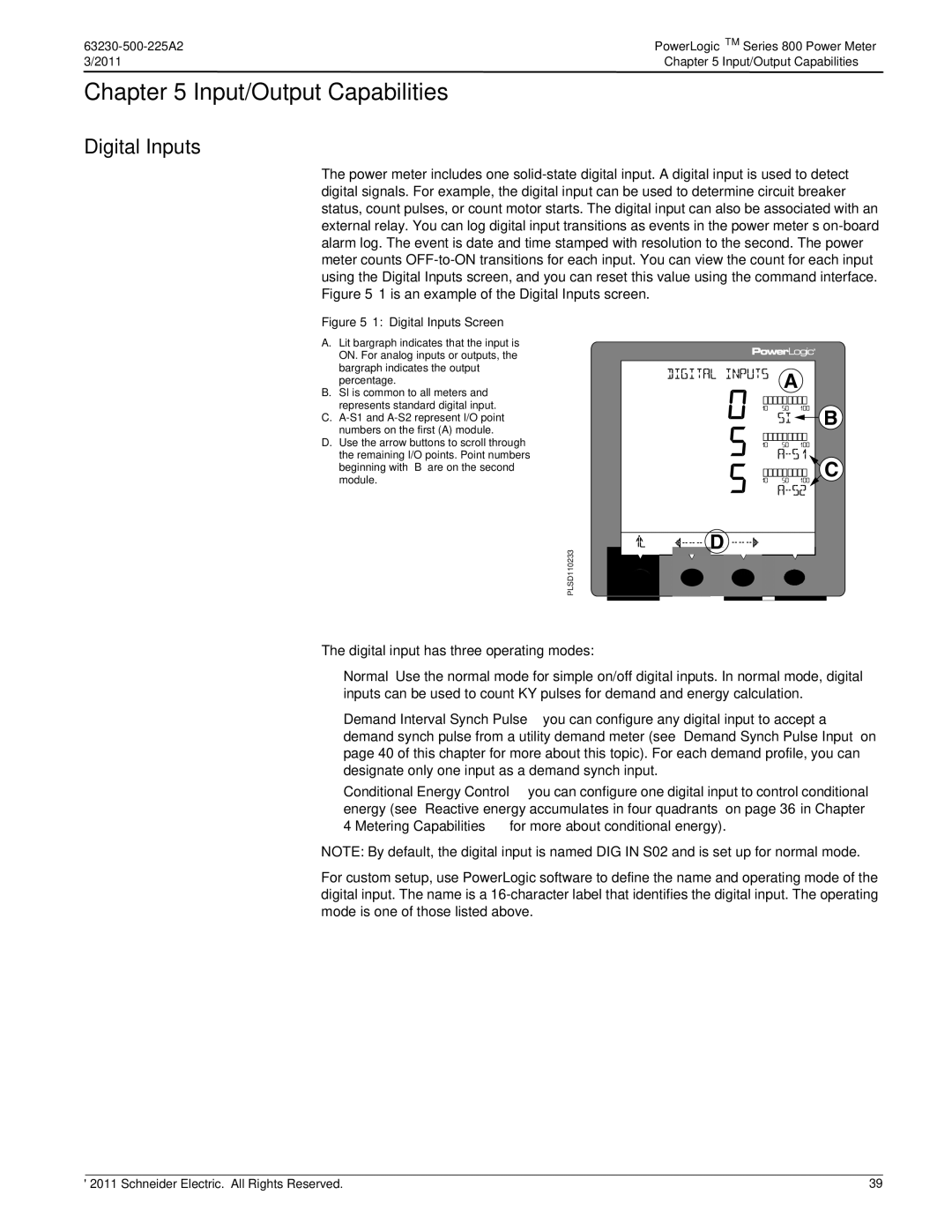
Digital Inputs
Input/Output Capabilities
Demand Synch Pulse Input
Normal Demand Mode External Synch Pulse Demand Timing
Relay Output Operating Modes
Normal
Latched
End Of Power Demand Interval
Timed
Absolute kWh Pulse
Solid-state KY Pulse Output
Wire Pulse Initiator
KWh Out Pulse
KVARh Out Pulse
Calculating the Kilowatthour-Per-Pulse Value
Fixed Pulse Output
Analog Inputs
Analog Outputs
= 0.1111 kWh/pulse
Basic Alarms
Alarms
Basic Alarm Groups
2011 Alarms
EV2Max2
Setpoint-driven Alarms
EV1Max1
Max2
Viewing Alarm Activity and History
Priorities
Types of Setpoint-controlled Functions
Schneider Electric. All Rights Reserved
Scale Groups Measurement Range Scale Factor
Scale Factors
Alarm Conditions and Alarm Numbers
Scaling Alarm Setpoints
Scale Group Register Numbers
Limit
Digital
Standard Speed Alarms 1 Second
Standard Speed
Advanced Alarm Groups
Advanced Alarms
Advanced alarm features by model
PM850 PM870
Alarm Levels
Abbreviated Test Display Name Register
Nand
Logging
Introduction
2011 Logging
Maintenance Log
Alarm Log
Alarm Log Storage
Memory Allocation for Log Files
Number
Value Stored
Registers
Data Logs
Billing Log
Alarm-driven Data Log Entries
Organizing Data Log Files PM850, PM870
Data Log
Page
Configure the Billing Log Logging Interval
2011 Logging Billing Log Register List Description
Data Type➀
Page
Waveform Capture
Waveform Capture
2011 Waveform Capture
Number Channels
Channel Selection in PowerLogic Software
How the Power Meter Captures an Event
Waveform Storage
Initiating a Waveform
63230-500-225A2 PowerLogicTM Series 800 Power Meter 2011
Disturbance Monitoring PM870
About Disturbance Monitoring
Transformer Plant C Plant D Fault
Plant a
Plant B
Capabilities of the PM870 During an Event
63230-500-225A2 PowerLogic TM Series 800 Power Meter 2011
Page
Maintenance and Troubleshooting
Power Meter Memory
Date and Time Settings
Identifying the Firmware Version, Model, and Serial Number
Viewing the Display in Different Languages
Technical Support
Heartbeat LED
Troubleshooting
CT and PT ratings, System Type, Nominal
What is Normal?
Using This Appendix
Section I-Case a
Section I Common Problems for 3-Wire and 4-Wire Systems
Section I-Case B
Section I-Case C
Section II 3-Wire System Troubleshooting
Section III-Case a
Section III 4-Wire System Troubleshooting
Section III-Case B
Section III-Case C
Section III-Case E
Section III-Case F
Section III-Case G
Readings from a 4-wire system
Troubleshooting Diagnosis
Field Example
Appendix B-Register List
Register List Access
About Registers
Floating-point Registers
How Date and Time are Stored in Registers
How Signed Power Factor is Stored in the Register
Table B-1 Date and Time Format
Table B-2 Date and Time Byte Example
Resetting Registers
Supported Modbus Commands
Table B-3 Modbus Commands
Table B-4 Register Listing-Reset Commands
Schneider Electric All Rights Reserved
Overview of the Command Interface
Appendix C-Using the Command Interface
Issuing Commands
Table C-2 Command Codes
Command
Files
Resets
Setup
Operating Outputs from the Command Interface
9020 None Enter into setup mode 9021 8001
Exit setup mode and save all changes
To save the changes, write the value 1 to register
Conditional Energy
Command Interface Control
Incremental Energy
Digital Input Control
Figure C-2 Incremental energy example
Using Incremental Energy
Setting Up Individual Harmonic Calculations
Enabling Floating-point Registers
Changing Scale Factors
Page
Power Quality Standards
Appendix D-Advanced Power Quality Evaluations
SEMI-F47/ITI Cbema Specification
Table D-2 Duration categories
PowerLogicTM Series 800 Power Meter 63230-500-225A2
Appendix D-Advanced Power Quality Evaluations
Table D-3 Categorized disturbance levels F-47 Sag levels
Table D-4 Duration categories
EN501602000 Specification
How Evaluation Results Are Reported
Table D-6 Register Entries Description Number
Power Frequency
Possible Configurations Through Register Writes
Evaluation During Normal Operation1
Supply Voltage Variations
Supply Voltage Unbalance
Evaluations During Abnormal Operation
Harmonic Voltage
Count of Magnitude of Rapid Voltage Changes
Table D-8 Voltage dip classifications
Detection of Interruptions of the Supply Voltage
Table D-9 Voltage interruptions Duration t seconds
Table D-10 Over-voltages Duration t seconds
Resetting Statistics
Operation with PQ Advanced Enabled
Harmonic Calculations
Time Intervals
100 Schneider Electric. All Rights Reserved
Table D-12 Portal Register Descriptions Size Data
Portal Registers
101
Detection and Classification of Supply Voltage Dips on
102 Schneider Electric. All Rights Reserved
Detecting and Classifying Temporary Power Frequency Over
103
Alarms Allocated for PQ Advanced Evaluations
Setting Up PQ Advanced Evaluation from the Display
Terms
Glossary
63230-500-225A2 3/2011
105
106 Schneider Electric. All Rights Reserved
Abbreviations and Symbols
2011 Glossary
107
108 Schneider Electric. All Rights Reserved
Index
PowerLogicTM Series 800 Power Meter Index
63230-500-225A2 3/2011
109
110
111
PLC
112
VAR
Page
PowerLogic Power Meter 800 User Guide