TigerSwitch 10/100
Page
TigerSwitch 10/100 Installation Guide
Trademarks
Limited Warranty
SMC Networks, Inc Tesla Irvine, CA
Contents
Page
Iii
Command Line Interface
Contents
Page
Vii
Viii
Contents
Appendix a Software Specifications
Tables
Xii
Figures
Xiii
Figures
Xiv
Feature Description
Key Features
Key Features
Supports standard STP and Rapid Spanning Tree Protocol Rstp
Description of Software Features
Description of Software Features
Introduction
Function Parameter Default
System Defaults
System Defaults
Password super
System Defaults Function Parameter
Pvid
Client Enabled
Clock Synchronization Disabled
Introduction
Connecting to the Switch
Configuration Options
Initial Configuration
Required Connections
Console Connection
Basic Configuration
Remote Connections
Manual Configuration
Setting Passwords
Setting an IP Address
Dynamic Configuration
Enabling Snmp Management Access
Community Strings
Saving Configuration Settings
Trap Receivers
Managing System Files
Enter the name of the start-up file. Press Enter
Configuring the Switch
Using the Web Interface
Navigating the Web Browser Interface
Home
Configuration Options
Panel Display
Main Menu
Reset Restarts the switch
Configuration
Main Menu Description
ACL
105
101
Current Table
110
117
Class-of-service value IP Dscp Priority
Matching an ACL rule Igmp Snooping 132 Igmp Configuration
126
Displaying System Information
Field Attributes
Displaying Switch Hardware/Software Versions
CLI Specify the hostname, location and contact information
Displaying Switch Information
Displaying Bridge Extension Configuration
Displaying Bridge Extension Capabilities
Command Attributes
Setting the Switch’s IP Address
CLI Enter the following command
IP Configuration
Using DHCP/BOOTP
IP Configuration using Dhcp
Managing Firmware
Downloading System Software from a Server
Operation Code Image File Transfer
Saving or Restoring Configuration Settings
10. Deleting Files
Downloading Configuration Settings from a Server
11. Copy Configuration Settings
Console Port Settings
12. Setting the Startup Configuration Settings
13. Console Port Settings
Telnet Settings
14. Enabling Telnet
Configuring Event Logging
System Log Configuration
Level Severity Name Description
Error resource exhausted
Logging Levels
Alert Immediate action needed Emergency System unusable
Remote Logs Configuration
16. Enabling Remote Logging and Adding Host IP Addresses
Displaying Log Messages
17. Displaying System Logs
Resetting the System
Setting the System Clock
Configuring Sntp
19. Configuring Sntp
Setting the Time Zone
Simple Network Management Protocol
Setting Community Access Strings
Access Mode
22. Configuring IP Trap Managers
Specifying Trap Managers and Trap Types
User Authentication
Configuring User Accounts
23. Access Levels
Configuring Local/Remote Logon Authentication
Command Usage
Radius Settings
Tacacs Settings
24. Authentication Settings
Configuring Https
Compatible Operating Systems Web Browser
Replacing the Default Secure-site Certificate
25. Https Settings
Configuring the Secure Shell
Configuring the Switch
Generating the Host Key Pair
26. SSH Host-Key Settings
Configuring the SSH Server
SSH server includes basic settings for authentication
Configuring Port Security
28. Configuring Port Security
Configuring 802.1x Port Authentication
CLI This example shows the default global setting for
Displaying 802.1x Global Settings
802.1x protocol provides client authentication
Web Click Security, 802.1X, Information
CLI This example enables 802.1x globally for the switch
Configuring 802.1x Global Settings
Configuring Port Settings for
31 .1x Port Configuration
Authorized
Consoleconfig#interface ethernet 1/2
Displaying 802.1x Statistics
Statistical Values 1x Statistics Parameter Description
32. Displaying 802.1x Port Statistics
CLI This example displays the 802.1x statistics for port
Access Control Lists
Configuring Access Control Lists
Setting the ACL Name and Type
CLI This example creates a standard IP ACL named david
Configuring a Standard IP ACL
34. Configuring Standard ACLs
Configuring an Extended IP ACL
35. Configuring Extended ACLs
Configuring a MAC ACL
36. Configuring MAC ACLs
Binding a Port to an Access Control List
37. Binding a Port to an ACL
Filtering Addresses for Management Access
CLI This example allows Snmp access for a specific client
38. Creating a Web IP Filter List
Field Attributes Web
Port Configuration
Displaying Connection Status
Web Click Port, Port Information or Trunk Information
Field Attributes CLI
Basic Information
Configuring Interface Connections
CLI This example shows the connection status for Port
40. Port/Trunk Configuration
Creating Trunk Groups
Statically Configuring a Trunk
41. Configuring Port Trunks
Enabling Lacp on Selected Ports
120
42. Lacp Configuration
Configuring Lacp Parameters
Dynamically Creating a Port Channel
43. Lacp Port Configuration
122
Field Description
Displaying Lacp Port Counters
Lacp Statistics
Displaying Lacp Settings and Status for the Local Side
Displaying Lacp Local Settings
45. Displaying Lacp Port Internal Information
Displaying Lacp Settings and Status for the Remote Side
Displaying Lacp Remote Settings Field Description
Setting Broadcast Storm Thresholds
47. Enabling Port Broadcast Control
Configuring Port Mirroring
48. Mirror Port Configuration
Configuring Rate Limits
Rate Limit Granularity
Rate Limit Configuration
50. Output Rate Limit Port Configuration
Showing Port Statistics
Parameter Description
Port Statistics
Parameter Description
Oversize Frames
Or alignment error
Formed
Fragments
51. Port Statistics
CLI This example shows statistics for port
Address Table Settings
Setting Static Addresses
52. Configuring a Static Address Table
Displaying the Address Table
53. Configuring a Dynamic Address Table
CLI This example sets the aging time to 400 seconds
Spanning Tree Algorithm Configuration
Changing the Aging Time
Displaying Global Settings
Spanning Tree Algorithm Configuration
55. Displaying Spanning Tree Information
Configuring Global Settings
Global settings apply to the entire switch
Configuration Settings for Rstp
56. Configuring Spanning Tree
Displaying Interface Settings
57. Bpdu Transmission
58. Displaying Spanning Tree Information
CLI This example shows the STA attributes for port
Configuring Interface Settings
59. Configuring Spanning Tree per Port
CLI This example sets STA attributes for port
Vlan Configuration
Ieee 802.1Q VLANs
VA Vlan Aware VU Vlan Unaware
Forwarding Tagged/Untagged Frames
Displaying Basic Vlan Information
Enabling or Disabling Gvrp Global Setting
CLI This example enables Gvrp for the switch
Web Click VLAN, 802.1Q VLAN, Basic Information
Command Attributes Web
Displaying Current VLANs
62. Displaying Current VLANs Command Attributes CLI
Creating VLANs
153
Adding Static Members to VLANs Vlan Index
CLI This example creates a new Vlan
64. Configuring a Vlan Static Table
Adding Static Members to VLANs Port Index
65. Vlan Static Membership by Port
Configuring Vlan Behavior for Interfaces
66. Configuring VLANs per Port
Private VLANs
Displaying Current Private VLANs
67. Private Vlan Information
Configuring Private VLANs
Associating Community VLANs
Each community Vlan must be associated with a primary Vlan
Displaying Private Vlan Interface Information
69. Private Vlan Association
Configuring Private Vlan Interfaces
70. Displaying Private Vlan Port Information
71. Private Vlan Port Configuration
Setting the Default Priority for Interfaces
Class of Service Configuration
Layer 2 Queue Settings
72. Port Priority Configuration
CLI This example assigns a default priority of 5 to port
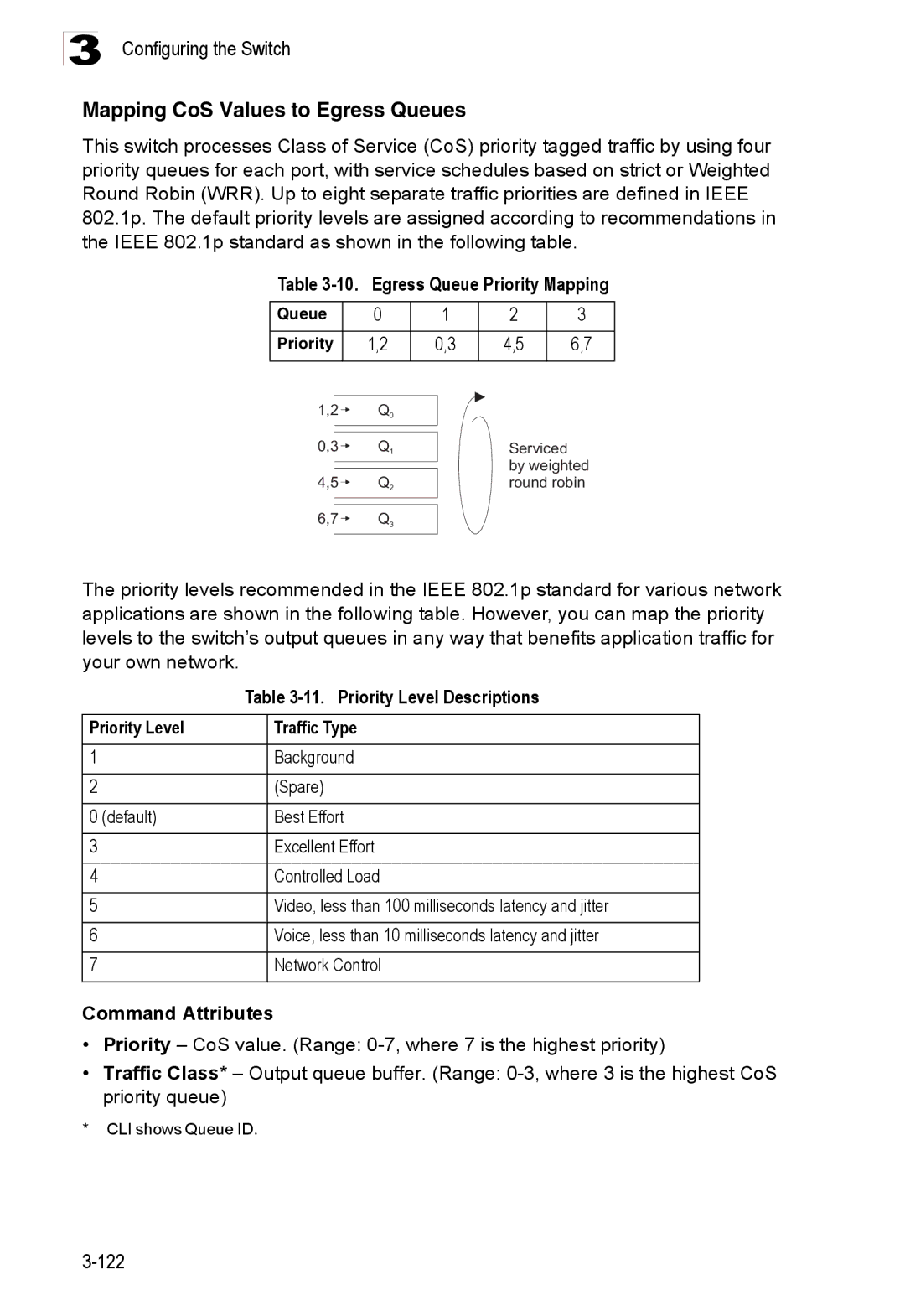
11. Priority Level Descriptions
Mapping CoS Values to Egress Queues
10. Egress Queue Priority Mapping
Priority Level Traffic Type
Selecting the Queue Mode
73. Traffic Classes
Setting the Service Weight for Traffic Classes
74. Selecting the Queue Mode
75. Configuring Interfaces for Queue Scheduling
Selecting IP Precedence/DSCP Priority
Layer 3/4 Priority Settings
Mapping Layer 3/4 Priorities to CoS Values
Mapping IP Precedence
12. Mapping IP Precedence Priority Level Traffic Type
10, 12, 14 18, 20, 22 26, 28, 30, 32, 34 38, 40
Mapping Dscp Priority
13. Mapping Dscp Priority Values IP Dscp Value CoS Value
78. Mapping IP Dscp Priority Values
Mapping IP Port Priority
79. Enabling IP Port Priority Status
Mapping CoS Values to ACLs
14. Egress Queue Priority Mapping
Multicast Filtering
81. ACL CoS Priority
Configuring Igmp Snooping and Query Parameters
Layer 2 Igmp Snooping and Query
82. Igmp Configuration
Displaying Interfaces Attached to a Multicast Router
83. Displaying Multicast Router Port Information
84. Static Multicast Router Port Configuration
Specifying Static Interfaces for a Multicast Router
Displaying Port Members of Multicast Services
85. IP Multicast Registration Table
Assigning Ports to Multicast Services
86. Igmp Member Port Table
Consoleconfig#ip igmp snooping vlan 1 static Ethernet 1/12
Configuring the Switch 140
Telnet Connection
Using the Command Line Interface
Accessing the CLI
Command Line Interface
Getting Help on Commands
Entering Commands
Command Completion
Keywords and Arguments
Showing Commands
Understanding Command Modes
Negating the Effect of Commands
Using Command History
Command Modes
Exec Commands
Configuration Commands
Configuration Modes Command Prompt
Consoleconfig-if# 104
Erases a mistake when entering a command
Command Line Processing
Command Line Processing
Keystroke Function
Command Groups
Command Groups Description
Line Commands
Line
Syntax Login local no login
Login
Related Commands
Example
Syntax Password 0 7 password no password
Password
Username 4-26 password
No password is specified
Syntax Timeout login response seconds no silent-time
Timeout login response
Exec-timeout
Syntax Exec-timeout seconds no exec-timeout
Syntax Password-thresh threshold no password-thresh
Password-thresh
Silent-time4-15 Timeout login response
Default value is three attempts
Syntax Silent-time seconds no silent-time
Silent-time
Databits
Syntax Databits 7 8 no databits
Parity
Syntax Parity none even odd no parity
Syntax Speed bps no speed
Speed
Stopbits
Syntax Stopbits 1
Syntax Disconnect session-id
Disconnect
Show line
Syntax Show line console vty
To show all lines, enter this command
General Commands
Enable
General Commands Function Mode
Enable
Disable
Disable Enable password
Level
Configure
Show history
Reload
End
Exit
This command exits the configuration program
This example shows how to quit a CLI session
Quit
Prompt
System Management Commands
Device Designation Commands
Hostname
User Access Commands
User Access Commands Function Mode
Syntax Hostname name no hostname
Username
10. Default Login Settings Username Access-level Password
Guest Admin
Enable password
Default is level Default password is super
Management
IP Filter Commands
11. IP Filter Commands Function Mode
Management
Show management
Ip http server
Web Server Commands
Ip http port
Ip http port
Syntax No ip http secure-server Default Setting
Ip http secure-server
13. Https System Support Web Browser Operating System
Portnumber The UDP port used for HTTPS/SSL. Range
Ip http secure-port
Ip http secure-port4-32 Copy tftp https-certificate
Ip http secure-server4-31
Ip telnet server
Telnet Server Commands
Ip telnet port
Ip telnet port
Secure Shell Commands
15. SSH Commands Function Mode
Sets the SSH server key size Copy tftp public-key
System Management Commands
Ip ssh crypto host-key generate 4-39 show ssh
Syntax Ip ssh server no ip ssh server Default Setting
Ip ssh server
Syntax Ip ssh timeout seconds no ip ssh timeout
Ip ssh timeout
Ip ssh authentication-retries
Exec-timeout4-13 show ip ssh
Syntax Delete public-key username dsa rsa
Ip ssh server-key size
Delete public-key
Syntax Ip ssh crypto host-key generate dsa rsa
Ip ssh crypto host-key generate
Ip ssh crypto zeroize
Syntax Ip ssh crypto zeroize dsa rsa
Syntax Ip ssh save host-key dsa rsa
Ip ssh save host-key
Show ip ssh
Show ssh
16. show ssh display description
Username Name of an SSH user. Range 1-8 characters
Show public-key
Syntax Show public-key user username host
Shows all public keys
Syntax No logging on Default Setting
Event Logging Commands
17. Event Logging Commands Function Mode
Logging on
18. Logging Levels
Flash errors level 3 RAM warnings level 7
Logging history
Syntax No logging host hostipaddress
Logging host
Logging facility
Hostipaddress The IP address of a syslog server
Syntax Logging trap level no logging trap
Logging trap
Clear logging
Syntax Clear logging flash ram
Following example shows sample messages stored in RAM
Show log
Syntax Show log flash ram
Syntax Show logging flash ram trap
This command displays the logging configuration
Show logging
19. show logging flash/ram display description
Logging trap command
Time Commands
Facility command
21. Time Commands Function Mode
Sntp server 4-51 sntp poll 4-51 show sntp
Syntax No sntp client Default Setting
Sntp client
Syntax Sntp server ip1 ip2 ip3
Sntp server
Sntp poll
Sntp client 4-50 sntp poll 4-51 show sntp
Sntp client
Show sntp
Clock timezone
Show calendar
This command displays the system clock
Calendar set
Syntax
Light unit
System Status Commands
22. System Status Commands Function Mode
Syntax Light unit unit
Show startup-config
Show running-config
Show running-config4-56
Show startup-config4-55
Show users
This command displays system information
Show system
Show version
Jumbo frame Enables support for jumbo frames
Frame Size Commands
23. Frame Size Commands Function Mode
Syntax No jumbo frame Default Setting
Copy
Flash/File Commands
24. Flash/File Commands Function Mode
None
Following example shows how to download a configuration file
Dir
Syntax Dir unit boot-rom config opcode filename
Delete
Syntax whichboot unit
Whichboot
Following example shows how to display all file information
25. File Directory Information
Dir 4-64 whichboot
Boot system
Syntax Boot system unit boot-romconfig opcode filename
Authentication login
Authentication Commands
Authentication Sequence
26. Authentication Commands Command Group Function
Authentication enable
Username for setting the local user names and passwords
Radius Client
28. Radius Client Commands Function Mode
Show radius-server Shows the current Radius settings
Radius-server port
Default Setting Auth-port
Retransmit Command Mode
Syntax Radius-server port portnumber no radius-server port
Syntax Radius-server key keystring no radius-server key
Radius-server key
Radius-server retransmit
Radius-server timeout
Show radius-server
Tacacs-server host
29. Tacacs Commands Function Mode
TACACS+ Client
Tacacs-server port
Syntax Tacacs-server key keystring no tacacs-server key
Tacacs-server key
Show tacacs-server
Status Disabled Action None Maximum Addresses
Port Security Commands
30. Port Security Commands Function Mode
Interface Configuration Ethernet
Command Usage
Acquire a new client Dot1x timeout re-authperiod
802.1x Port Authentication
31 .1x Port Authentication Command Function Mode
Be re-authenticated Dot1x timeout tx-period
Default Command Mode
Dot1x default
Syntax Dot1x default Command Mode
Dot1x max-req
Force-authorized
Dot1x port-control
Dot1x operation-mode
Single-host
Syntax Dot1x re-authenticate interface
Dot1x re-authenticate
Dot1x re-authentication
Syntax No dot1x re-authentication Command Mode
Seconds The number of seconds. Range
Dot1x timeout quiet-period
Dot1x timeout re-authperiod
Syntax Show dot1x statistics interface interface
Dot1x timeout tx-period
Show dot1x
Authenticator State Machine
State Current state including initialize, reauthenticate
Command Line Interface
Access Control List Commands
Access Control Lists
33. IP ACLs Command Function Mode
Access-list ip
32. Access Control Lists Command Groups Function
Syntax No access-list ip standard extended aclname
Standard ACL
Permit, deny Ip access-group4-90 show ip access-list4-90
Syntax No permit deny any source bitmask host source
Access-list ip
No permit deny tcp
Extended ACL
Syntax Show ip access-list standard extended aclname
Show ip access-list
Ip access-group
Syntax No ip access-group aclname
Show ip access-list4-90
Show ip access-group
Map access-list ip
This command shows the ports assigned to IP ACLs
Syntax Show map access-list ip interface
Show map access-list ip
Queue cos-map4-166 Show map access-list ip
34. Egress Queue Priority Mapping
Syntax No access-list mac aclname
Access-list mac
35. MAC ACLs Command Function Mode
MAC ACLs
Permit, deny MAC ACL
Syntax No permit deny
Syntax Show mac access-list aclname
Show mac access-list
Mac access-group
Syntax Mac access-group aclname
Show mac access-list4-95
Show mac access-group
Map access-list mac
This command shows the ports assigned to MAC ACLs
Syntax Show map access-list mac interface
Show map access-list mac
Queue cos-map4-166 Show map access-list mac
36. Egress Queue Priority Mapping
37. ACL Information Command Function Mode
Show access-list
Show access-group
ACL Information
Snmp-server community
Snmp Commands
38. Snmp Commands Function Mode
Syntax Snmp-server contact string no snmp-server contact
Snmp-server contact
Snmp-server location
Syntax Snmp-server location text no snmp-server location
Snmp-server host
Host Address None Snmp Version
Issue authentication and link-up-down traps
Snmp-server enable traps
Snmp-server enable traps
This command checks the status of Snmp communications
103
Interface
Interface Commands
39. Interface Commands Function Mode
Port-channel channel-idRange
Syntax Description string no description
Description
Speed-duplex
Negotiation 4-106 capabilities
Syntax No negotiation Default Setting
Negotiation
Capabilities 4-107speed-duplex4-105
Following example configures port 11 to use autonegotiation
Capabilities
Flowcontrol
Syntax No flowcontrol Default Setting
Flow control enabled
Negotiation 4-106speed-duplex4-105 flowcontrol
Syntax No shutdown Default Setting
Shutdown
Port-channel channel-idRange Default Setting
Switchport broadcast packet-rate
This command clears statistics on an interface
Clear counters
Following example clears statistics on port
This command displays the status for an interface
Show interfaces status
Syntax Show interfaces status interface
Syntax Show interfaces counters interface
This command displays interface statistics
Show interfaces counters
Shows the counters for all interfaces
Shows all interfaces
Show interfaces switchport
Syntax Show interfaces switchport interface
40. Interfaces Switchport Statistics
Interface Configuration Ethernet, destination port
Mirror Port Commands
41. Mirror Port Commands Function Mode
Port monitor
Show port monitor
Syntax Show port monitor interface
Rate-limit
Rate Limit Commands
42. Rate Limit Commands Function Mode
Actual rate limit = Rate limit level * Granularity
Rate-limit granularity
Global Configuration Ethernet, Port Channel
Use this command to display the rate limit granularity
Show rate-limit
Link Aggregation Commands
43. Link Aggregation Commands
Syntax Channel-group channel-idno channel-group
Channel-group
Guidelines for Creating Trunks
Following example creates trunk 1 and then adds port
Syntax No lacp Default Setting
Lacp
Lacp system-priority
32768
Lacp admin-keyEthernet Interface
Lacp admin-key Port Channel
This command displays Lacp information
Lacp port-priority
Type
Port Channel all
44. show lacp counters display description
Badly formed PDU or an illegal value of Protocol Subtype
45. show lacp internal display description
46. show lacp neighbors display description
47. show lacp sysid display description
Address Table Commands
48. Address Table Commands Function Mode
Vlan-id- Vlan ID Range
Mac-address-table static
Mac-address- MAC address
Mac-address- MAC address Mask Bits to match in the address
Clear mac-address-table dynamic
Show mac-address-table
Mac-address-table aging-time
Show mac-address-table aging-time
Syntax No spanning-tree Default Setting
Spanning Tree Commands
49. Spanning Tree Commands Function Mode
Spanning tree is enabled
Rstp
Spanning-tree mode
Syntax Spanning-tree mode stp rstp no spanning-tree mode
Spanning-tree forward-time
Spanning-tree hello-time
Spanning-tree max-age
Long method
Spanning-tree priority
Spanning-tree pathcost method
Spanning-tree cost
This command limits the maximum transmission rate for BPDUs
Spanning-tree transmission-limit
Count The transmission limit in seconds. Range
Spanning-tree port-priority
Priority The priority for a port. Range 0-240, in steps
Syntax No spanning-tree edge-port Default Setting
Spanning-tree edge-port
Spanning-tree link-type
Syntax No spanning-tree portfast Default Setting
Spanning-tree portfast
Spanning-treeedge-port4-140
Auto
Port-channel channel-idRange Command Mode
Spanning-tree protocol-migration
Syntax Spanning-tree protocol-migration interface
Syntax Show spanning-tree interface
This command shows the configuration for the spanning tree
Show spanning-tree
144
51. Editing Vlan Groups Command Function Mode
Vlan Commands
50. VLANs Command Groups Function
Editing Vlan Groups
Vlan
By default only Vlan 1 exists and is active
Vlan Database Configuration
Show vlan
Interface vlan
Configuring Vlan Interfaces
52. Configuring Vlan Interfaces Command Function Mode
Interface vlan
All ports are in hybrid mode with the Pvid set to Vlan
Switchport mode
Switchport acceptable-frame-types
Switchport acceptable-frame-types4-148
Switchport ingress-filtering
Syntax No switchport ingress-filtering Default Setting
Switchport native vlan
Switchport allowed vlan
Switchport forbidden vlan
No VLANs are included in the forbidden list
Show vlan
53. Show Vlan Commands Function Mode
Displaying Vlan Information
Configuring Private VLANs
54. Private Vlan Commands Function Mode
Vlan Configuration
Private-vlan
No private-vlan primary-vlan-idassociation
Switchport mode private-vlan
Private vlan association
Switchport private-vlan host-association
Normal Vlan
Syntax Show vlan private-vlan community isolated primary
Switchport private-vlan mapping
Show vlan private-vlan
Syntax No bridge-ext gvrp Default Setting
Gvrp and Bridge Extension Commands
55. Gvrp and Bridge Extension Commands Function Mode
Bridge-ext gvrp
Show bridge-ext
Switchport gvrp
Syntax No switchport gvrp Default Setting
This command shows if Gvrp is enabled
Show gvrp configuration
Garp timer
Syntax Show gvrp configuration interface
Shows all Garp timers
Show garp timer
Syntax Show garp timer interface
56. Priority Commands Command Groups Function
Priority Commands
Priority Commands Layer
57. Priority Commands Layer Function Mode
Queue bandwidth
Queue mode
Syntax Queue mode strict wrr no queue mode
Switchport priority default
Queue cos-map
Mapping CoS Values
Show queue bandwidth
Show queue mode
This command shows the current queue mode
Show queue cos-map4-168
Syntax Show queue cos-map interface
This command shows the class of service priority map
Show queue cos-map
Syntax No map ip port Default Setting
Priority Commands Layer 3
59. Priority Commands Layer 3 Function Mode
Following example shows how to map Http traffic to CoS value
Syntax No map ip precedence Default Setting
List below shows the default priority mapping
60. Mapping IP Precedence Values CoS Value Command Mode
Command Line Interface Map ip dscp Global Configuration
Syntax No map ip dscp Default Setting
Syntax Show map ip port interface
Use this command to show the IP port priority map
61. IP Dscp to CoS Vales IP Dscp Value CoS Value
Syntax Show map ip precedence interface
This command shows the IP precedence priority map
Show map ip precedence
Syntax Show map ip dscp interface
This command shows the IP Dscp priority map
Show map ip dscp
62. Multicast Filtering Commands Command Groups Function
Multicast Filtering Commands
Igmp Snooping Commands
63. Igmp Snooping Commands Function Mode
Ip igmp snooping
Syntax No ip igmp snooping Default Setting
Following example enables Igmp snooping
Ip igmp snooping vlan static
Ip igmp snooping version
Following configures the switch to use Igmp Version
This command shows the Igmp snooping configuration
Show ip igmp snooping
Show mac-address-table multicast
Following shows the current Igmp snooping configuration
This command shows known multicast addresses
Syntax No ip igmp snooping querier Default Setting
Igmp Query Commands Layer
64. Igmp Query Commands Layer Function Mode
Ip igmp snooping querier
Times
Following shows how to configure the query count to
Ip igmp snooping query-interval
Ip igmp snooping query-max-response-time4-182
Ip igmp snooping router-port-expire-time
Seconds The report delay advertised in Igmp queries. Range
Ip igmp snooping query-max-response-time
Ip igmp snooping vlan mrouter
Static Multicast Routing Commands
65. Static Multicast Routing Commands Function Mode
Syntax No ip igmp snooping vlan vlan-idmrouter interface
Syntax Show ip igmp snooping mrouter vlan vlan-id
Displays multicast router ports for all configured VLANs
Show ip igmp snooping mrouter
Interface Configuration Vlan
IP Interface Commands
66. IP Interface Commands Function Mode
Ip address
This command submits a Bootp or Dhcp client request
Ip dhcp restart
Show ip interface
Ip default-gateway
Syntax Ip default-gateway gateway no ip default-gateway
Show ip redirects
Ip default-gateway4-187
This command has no default for the host
Ping
189
Command Line Interface 190
Appendix a Software Specifications
Software Features
Standards
Management Features
Groups 1, 2, 3, 9 Statistics, History, Alarm, Event
Management Information Bases
SNMPv2 RFC Sntp RFC SSH Version Tftp RFC
Software Specifications
Table B-1. Troubleshooting Chart
Symptom Action
Using System Logs
Class of Service CoS
Access Control List ACL
Boot Protocol Bootp
Differentiated Services Code Point Service Dscp
Generic Multicast Registration Protocol Gmrp
Garp Vlan Registration Protocol Gvrp
Generic Attribute Registration Protocol Garp
Group Attribute Registration Protocol Garp
Internet Group Management Protocol Igmp
Igmp Snooping
Igmp Query
In-Band Management
Remote Authentication Dial-in User Service Radius
Multicast Switching
Port Authentication
Network Time Protocol NTP
Simple Network Time Protocol Sntp
Secure Shell SSH
Simple Network Management Protocol Snmp
Spanning Tree Protocol STP
Virtual LAN Vlan
XModem
Downloading software 3-16,4-61
Gateway, default 3-12,4-187
Numerics
Index
Index-3
Index-4
Page
For Technical SUPPORT, Call