CHAPTER 1 Introduction
Hardware Description
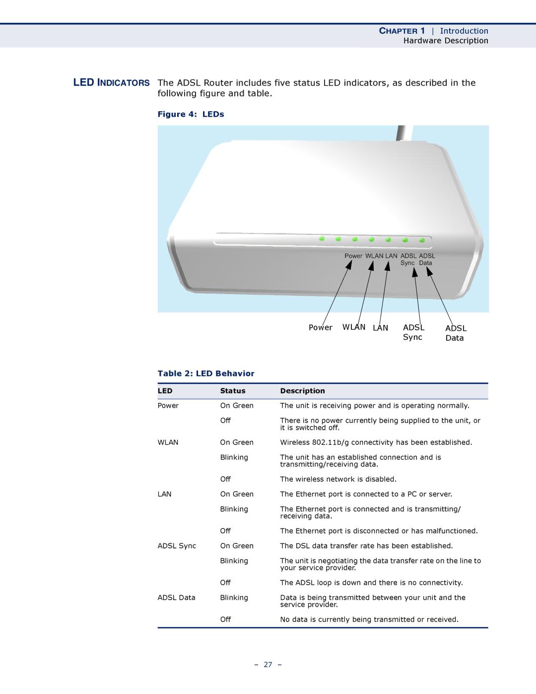
LED INDICATORS The ADSL Router includes five status LED indicators, as described in the following figure and table.
Figure 4: LEDs
|
| Power WLAN LAN | ADSL | ADSL |
|
|
| Sync | Data |
Table 2: LED Behavior |
|
|
| |
|
|
|
|
|
LED | Status | Description |
|
|
|
|
| ||
Power | On Green | The unit is receiving power and is operating normally. | ||
| Off | There is no power currently being supplied to the unit, or | ||
|
| it is switched off. |
|
|
WLAN | On Green | Wireless 802.11b/g connectivity has been established. | ||
| Blinking | The unit has an established connection and is |
| |
|
| transmitting/receiving data. |
|
|
| Off | The wireless network is disabled. |
|
|
LAN | On Green | The Ethernet port is connected to a PC or server. | ||
| Blinking | The Ethernet port is connected and is transmitting/ | ||
|
| receiving data. |
|
|
| Off | The Ethernet port is disconnected or has malfunctioned. | ||
ADSL Sync | On Green | The DSL data transfer rate has been established. | ||
| Blinking | The unit is negotiating the data transfer rate on the line to | ||
|
| your service provider. |
|
|
| Off | The ADSL loop is down and there is no connectivity. | ||
ADSL Data | Blinking | Data is being transmitted between your unit and the | ||
|
| service provider. |
|
|
| Off | No data is currently being transmitted or received. | ||
|
|
|
|
|
– 27 –