APPENDIX C Cables and Pinouts
RJ-11 PORTS
Standard telephone
The
The outer
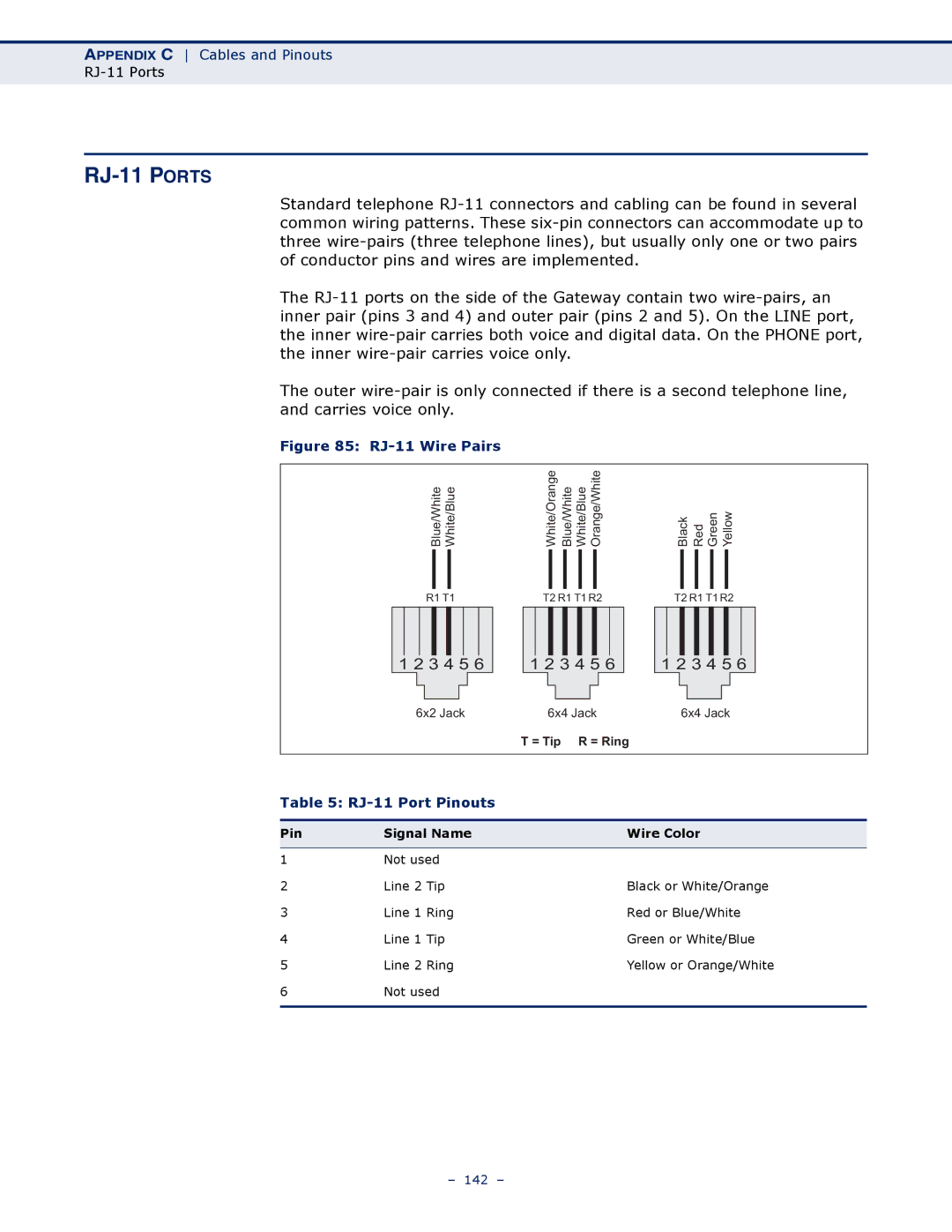
Figure 85: RJ-11 Wire Pairs
Blue/White White/Blue | White/Orange Blue/White White/Blue Orange/White | Black Red Green Yellow | ||||||||||
|
|
|
|
|
|
|
|
|
|
|
|
|
R1 T1 | T2 R1 T1 R2 | T2 R1 T1 R2 | ||||||||||
1 2 3 4 5 6
1 2 3 4 5 6
1 2 3 4 5 6
| 6x2 Jack | 6x4 Jack | 6x4 Jack | |
|
|
| T = Tip R = Ring | |
|
|
| ||
Table 5: |
|
| ||
|
|
|
| |
Pin | Signal Name |
| Wire Color | |
|
|
|
| |
1 | Not used |
|
| |
2 | Line 2 | Tip |
| Black or White/Orange |
3 | Line 1 | Ring |
| Red or Blue/White |
4 | Line 1 | Tip |
| Green or White/Blue |
5 | Line 2 | Ring |
| Yellow or Orange/White |
6 | Not used |
|
| |
|
|
|
|
|
– 142 –