Management Guide
Page
TigerSwitch 10/100/1000 Management Guide
Page
Contents
Page
Iii
Page
Command Line Interface
Page
Vii
Viii
Contents
Page
Contents
Xii
Glossary Index
Appendix a Software Specifications
Appendix B Troubleshooting
Xiii
Xiv
Tables
Xvi
Xvii
Xviii
Figures
Xix
Figures
Xxi
Xxii
Feature Description
Key Features
Key Features
Description of Software Features
Introduction
Description of Software Features
Introduction
Description of Software Features
Function Parameter Default
System Defaults
System Defaults
System Defaults Function Parameter
Client Enabled
Sntp
Connecting to the Switch
Configuration Options
Initial Configuration
Required Connections
Console Connection
Basic Configuration
Remote Connections
Manual Configuration
Setting Passwords
Setting an IP Address
Dynamic Configuration
Enabling Snmp Management Access
Trap Receivers
Saving Configuration Settings
Configuring Access for Snmp Version 3 Clients
Managing System Files
Initial Configuration
Configuring the Switch
Using the Web Interface
Navigating the Web Browser Interface
Home
Button
Configuration Options Action
Panel Display
Revert Apply Help
System System Information
Main Menu
Main Menu Description
Configuration Allows ports to dynamically join trunks
ACL
STA
116
Current Table
Class-of-service value
122
131
Configuration Settings
Query Igmp Filter Configuration
Configuration Settings Igmp Filter/Throttling Trunk
152
Cache
Dhcp Snooping 186 Configuration
183
185
Displaying System Information
Field Attributes
Main Board
Displaying Switch Hardware/Software Versions
CLI Specify the hostname, location and contact information
Management Software
Web Click System, Switch Information
Switch Information
Bridge Extension Configuration
Displaying Bridge Extension Capabilities
Command Attributes
Setting the Switch’s IP Address
CLI Enter the following command
Manual IP Configuration
Using DHCP/BOOTP
Dhcp IP Configuration
Enabling Jumbo Frames
Managing Firmware
Downloading System Software from a Server
Copy Firmware
Saving or Restoring Configuration Settings
11 Deleting Files
Downloading Configuration Settings from a Server
12 Downloading Configuration Settings for Startup
Console Port Settings
13 Setting the Startup Configuration Settings
14 Console Port Settings
Telnet Settings
15 Enabling Telnet
Configuring Event Logging
Displaying Log Messages
CLI This example shows the event message stored in RAM
System Log Configuration
Error resource exhausted
Logging Levels
Remote Log Configuration
17 System Logs
Simple Mail Transfer Protocol
18 Remote Logs
19 Enabling and Configuring Smtp
Resetting the System
Renumbering the System
Setting the System Clock
Configuring Sntp
Setting the Time Zone
23 Setting the System Clock
Simple Network Management Protocol
Setting Community Access Strings
Access Mode
24 Configuring Snmp Community Strings
Specifying Trap Managers and Trap Types
25 Configuring IP Trap Managers
Enabling Snmp Agent Status
CLI This example sets an SNMPv3 engine ID
Configuring SNMPv3 Management Access
Setting the Local Engine ID
CLI This example specifies a remote SNMPv3 engine ID
Configuring SNMPv3 Users
Specifying a Remote Engine ID
Configuring the Switch
29 Configuring SNMPv3 Users
Configuring Remote SNMPv3 Users
30 Configuring Remote SNMPv3 Users
Supported Notification Messages
Configuring SNMPv3 Groups
Topology Change Timer immediately
Subsequent to its election
SNMPv2 Traps
Rmon Events
Mode PethPsePortPower 6.1.4.1.202.20.68.2.1.0.1
Private Traps SwPowerStatus 6.1.4.1.202.20.68.2.1.0.1
PD Powered Device. This notification is
ChangeTrap SwIpFilterRejectTrap 6.1.4.1.202.20.68.2.1.0.1
31 Configuring SNMPv3 Groups
Setting SNMPv3 Views
32 Configuring SNMPv3 Views
User Authentication
Configuring User Accounts
33 Access Levels
Configuring Local/Remote Logon Authentication
Command Usage
Radius Settings
Tacacs Settings
34 Authentication Settings
User Authentication
Configuring Https
Https System Support Web Browser Operating System
Replacing the Default Secure-site Certificate
Configuring the Secure Shell
User Authentication
Configuring the SSH Server
SSH server includes basic settings for authentication
Generating the Host Key Pair
37 SSH Host-Key Settings
Configuring Port Security
Configuring 802.1X Port Authentication
38 Configuring Port Security
Displaying 802.1X Global Settings
802.1X protocol provides client authentication
CLI This example enables 802.1X globally for the switch
Configuring 802.1X Global Settings
CLI This example shows the default global setting for
Web Click Security, 802.1X, Information
Configuring Port Settings for
Authorized
41 802.1X Port Configuration
Consoleconfig#interface ethernet 1/2
Parameter Description
Displaying 802.1X Statistics
802.1X Statistics
CLI This example displays the 802.1X statistics for port
Access Control Lists
Configuring Access Control Lists
Setting the ACL Name and Type
CLI This example creates a standard IP ACL named david
Configuring a Standard IP ACL
Configuring an Extended IP ACL
Configuring the Switch
45 Configuring Extended IP ACLs
Configuring a MAC ACL
Binding a Port to an Access Control List
This switch supports ACLs for ingress filtering only
Filtering IP Addresses for Management Access
47 Configuring ACL Port Binding
48 Creating an IP Filter List
Displaying Connection Status
Port Configuration
CLI This example allows Snmp access for a specific client
Field Attributes Web
Basic Information
Configuration
Web Click Port, Port Information or Trunk Information
Configuring Interface Connections
Current Status
50 Port/Trunk Configuration
Creating Trunk Groups
Statically Configuring a Trunk
51 Configuring Static Trunks
Enabling Lacp on Selected Ports
131
52 Lacp Trunk Configuration
Configuring Lacp Parameters
Dynamically Creating a Port Channel
53 Lacp Port Configuration
Lacp Port Counters
Displaying Lacp Port Counters
You can display statistics for Lacp protocol messages
Field Description
54 Lacp Port Counters Information
CLI The following example displays Lacp counters
Displaying Lacp Settings and Status for the Local Side
Lacp Internal Configuration Information
55 Lacp Port Internal Information
Displaying Lacp Settings and Status for the Remote Side
Lacp Neighbor Configuration Information Field Description
Setting Broadcast Storm Thresholds
57 Port Broadcast Control
Configuring Port Mirroring
58 Mirror Port Configuration
Configuring Rate Limits
Rate Limit Configuration
Showing Port Statistics
10 Port Statistics
Etherlike Statistics
Resources Jabbers
Or alignment error Received Bytes
Rmon Statistics Drop Events
Formed Oversize Frames
60 Port Statistics
CLI This example shows statistics for port
Address Table Settings
Setting Static Addresses
61 Configuring a Static Address Table
Displaying the Address Table
62 Configuring a Dynamic Address Table
CLI This example sets the aging time to 300 seconds
Spanning Tree Algorithm Configuration
Changing the Aging Time
Spanning Tree Algorithm Configuration
104
Displaying Global Settings
64 Displaying Spanning Tree Information
Configuring Global Settings
Global settings apply to the entire switch
Basic Configuration of Global Settings
Root Device Configuration
Configuration Settings for Rstp
Configuration Settings for Mstp
65 Configuring Spanning Tree
Displaying Interface Settings
112
66 Displaying Spanning Tree Port Information
CLI This example shows the STA attributes for port
Configuring Interface Settings
67 Configuring Spanning Tree per Port
CLI This example sets STA attributes for port
Configuring Multiple Spanning Trees
68 Configuring Multiple Spanning Trees
Displaying Interface Settings for Mstp
MST Instance ID Instance identifier to configure. Default
69 Displaying Mstp Interface Settings
Configuring Interface Settings for Mstp
121
CLI This example sets the Mstp attributes for port
Vlan Configuration
Ieee 802.1Q VLANs
Assigning Ports to VLANs
124
Forwarding Tagged/Untagged Frames
Enabling or Disabling Gvrp Global Setting
CLI This example enables Gvrp for the switch
Displaying Current VLANs
Command Attributes Web
Displaying Basic Vlan Information
73 Displaying Current VLANs Command Attributes CLI
Creating VLANs
175
Adding Static Members to VLANs Vlan Index
CLI This example creates a new Vlan
130
75 Configuring a Vlan Static Table
Adding Static Members to VLANs Port Index
Configuring Vlan Behavior for Interfaces
Configuring Ieee 802.1Q Tunneling
77 Configuring VLANs per Port
Layer 2 Flow for Packets Coming into a Tunnel Access Port
Layer 2 Flow for Packets Coming into a Tunnel Uplink Port
Configuration Limitations for QinQ
General Configuration Guidelines for QinQ
Enabling QinQ Tunneling on the Switch
78 802.1Q Tunnel Status
CLI This example sets the switch to operate in QinQ mode
Adding an Interface to a QinQ Tunnel
79 Tunnel Port Configuration
45-1
Enabling Private VLANs
Configuring Private VLANs
CLI This example enables private VLANs
Protocol VLANs
Configuring Uplink and Downlink Ports
Protocol Vlan Group Configuration
Configuring Protocol Vlan Interfaces
82 Protocol Vlan Configuration
Setting the Default Priority for Interfaces
Class of Service Configuration
Layer 2 Queue Settings
Mapping CoS Values to Egress Queues
Port Priority Configuration
CLI This example assigns a default priority of 5 to port
11 Mapping CoS Values to Egress Queues
Background
12 CoS Priority Levels
Priority Level Traffic Type
Spare
Selecting the Queue Mode
Enabling CoS
Setting the Service Weight for Traffic Classes
87 Queue Mode
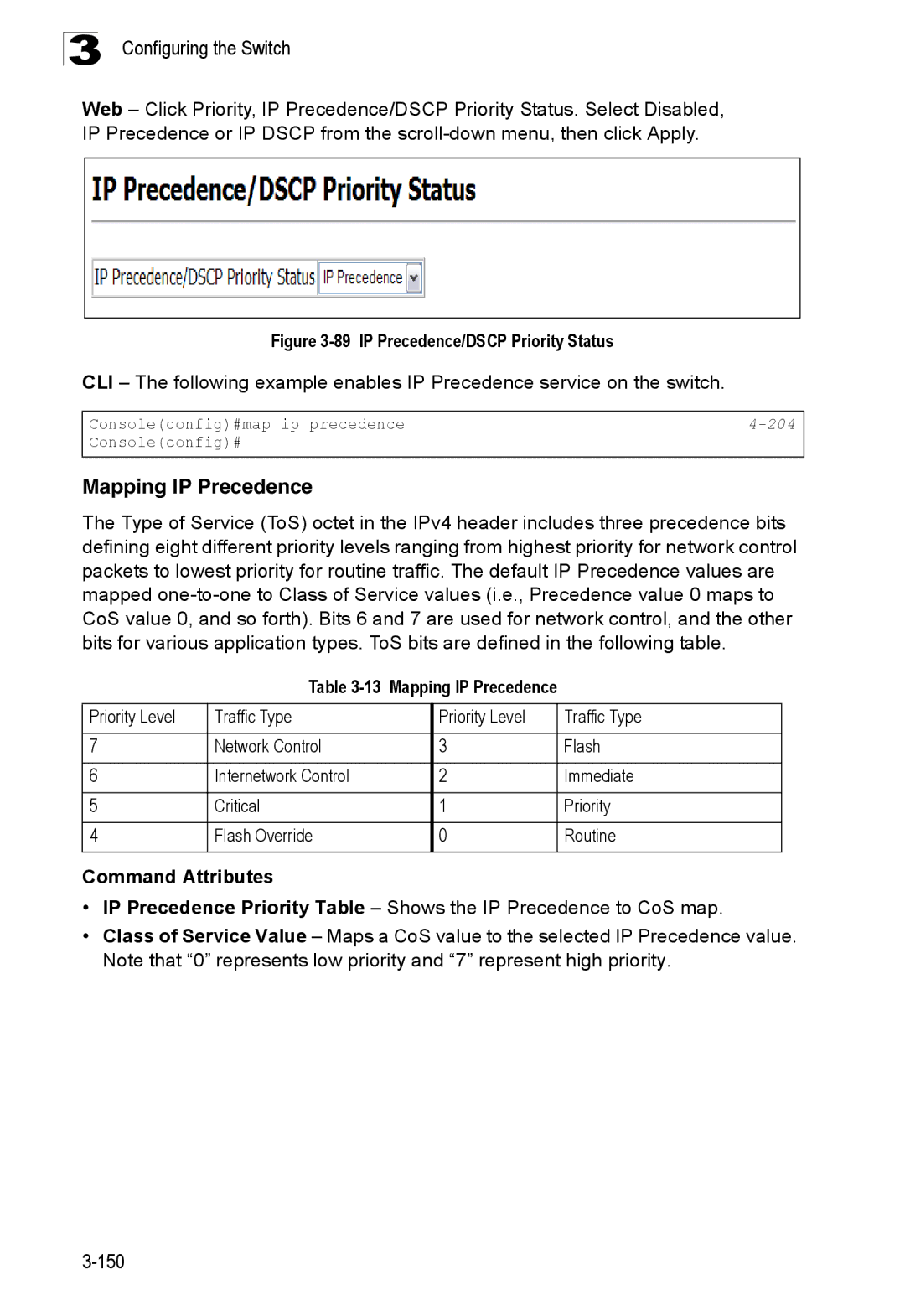
Selecting IP Precedence/DSCP Priority
Layer 3/4 Priority Settings
Mapping Layer 3/4 Priorities to CoS Values
Mapping IP Precedence
13 Mapping IP Precedence
90 Mapping IP Precedence Priority Values
IP Dscp Value CoS Value
Mapping Dscp Priority
14 Mapping Dscp Priority Values
10, 12, 14 18, 20, 22 26, 28, 30, 32, 34 38, 40
Mapping IP Port Priority
92 IP Port Priority Status
Quality of Service
93 IP Port Priority
Class map is used for matching packets to a specified class
Configuring Quality of Service Parameters
Configuring a Class Map
Class Map
Class Configuration
Match Class Settings
94 Configuring Class Maps
Policy Map
Policy Configuration
Creating QoS Policies
Policy Rule Settings Class Settings
Policy Options
95 Configuring Policy Maps
96 Service Policy Settings
Attaching a Policy Map to Ingress Queues
Multicast Filtering
Layer 2 Igmp Snooping and Query
Configuring Igmp Snooping and Query Parameters
97 Igmp Configuration
Enabling Igmp Immediate Leave
Displaying Interfaces Attached to a Multicast Router
98 Igmp Immediate Leave
Specifying Static Interfaces for a Multicast Router
99 Displaying Multicast Router Port Information
Displaying Port Members of Multicast Services
100 Static Multicast Router Port Configuration
Assigning Ports to Multicast Services
101 IP Multicast Registration Table
Igmp Filtering and Throttling
102 Igmp Member Port Table
Enabling Igmp Filtering and Throttling
103 Enabling Igmp Filtering and Throttling
Configuring Igmp Filtering and Throttling for Interfaces
Configuring Igmp Filter Profiles
104 Igmp Filter and Throttling Port Configuration
105 Igmp Profile Configuration
Multicast Vlan Registration
Configuring Global MVR Settings
General Configuration Guidelines for MVR
106 MVR Global Configuration
Displaying MVR Interface Status
Web Click MVR, Port or Trunk Information
107 MVR Port Information
Displaying Port Members of Multicast Groups
108 MVR Group IP Information
Configuring MVR Interface Status
MVR Vlan
Web Click MVR, Port or Trunk Configuration
Assigning Static Multicast Groups to Interfaces
Configuring Domain Name Service
Configuring General DNS Service Parameters
111 DNS General Configuration
Configuring Static DNS Host to Address Entries
238
112 DNS Static Host Table
Displaying the DNS Cache
113 DNS Cache
Dhcp Snooping
Dhcp Snooping Configuration
Web Click Dhcp Snooping, Configuration
Enables Dhcp snooping on the specified Vlan
Dhcp Snooping Vlan Configuration
Dhcp Snooping Information Option Configuration
CLI This example first enables Dhcp Snooping for Vlan
Dhcp Snooping Port Configuration
Trust Status Enables or disables port as trusted
117 Dhcp Snooping Port Configuration
Dhcp Snooping Binding Information
Web Click Dhcp Snooping, Dhcp Snooping Binding Information
IP Source Guard Port Configuration
IP Source Guard
Static IP Source Guard Binding Configuration
119 IP Source Guard Port Configuration
120 Static IP Source Guard Binding Configuration
Dynamic IP Source Guard Binding Information
Switch Clustering
Web Click IP Source Guard, Dynamic Information
Cluster Configuration
122 Cluster Member Choice
Adds Candidate switches to the cluster as Members
Cluster Member Configuration
Web Click Cluster, Configuration
Cluster Member Information
Web Click Cluster, Member Configuration
Displays current cluster Member switch information
Cluster Candidate Information
126 Cluster Candidate Information
Using the Command Line Interface
Accessing the CLI
Telnet Connection
Getting Help on Commands
Entering Commands
Command Completion
Keywords and Arguments
Showing Commands
Understanding Command Modes
Negating the Effect of Commands
Using Command History
Partial Keyword Lookup
Exec Commands
Command Modes
Consoleconfig-if# 120
Configuration Commands
Configuration Modes Command Prompt
Keystroke Function
Command Line Processing
Command Line Processing
Command Groups
Command Groups Description
Line Commands
Line Commands Function Mode
Login
Line
Syntax Password 0 7 password no password
Password
Username 4-25 password
No password is specified
Timeout login response
Exec-timeout
Syntax Password-thresh threshold no password-thresh
Password-thresh
Syntax Exec-timeout seconds no exec-timeout
Syntax Silent-time seconds no silent-time
Silent-time
Databits
Syntax Parity none even odd no parity
Parity
Syntax Databits 7 8 no databits
Syntax Speed bps no speed
Speed
Stopbits
Syntax Stopbits 1
Syntax Disconnect session-id
Disconnect
Show line
Syntax Show line console vty
To show all lines, enter this command
General Commands
Enable
General Commands Function Mode
Enable
Disable
Disable Enable password
Level
Configure
Show history
Reload
End
Exit
This command exits the configuration program
This example shows how to quit a CLI session
Quit
Prompt
System Management Commands
Device Designation Commands
Hostname
User Access Commands
User Access Commands Function Mode
Username
Guest Admin
Enable password
10 Default Login Settings Username Access-level Password
Management
IP Filter Commands
11 IP Filter Commands Function Mode
Show management
All addresses
Default Setting Command Mode
Web Server Commands
12 Web Server Commands Function Mode
Ip http port
Ip http server
Syntax No ip http server Default Setting
Syntax No ip http secure-server Default Setting
Ip http secure-server
Ip http secure-port4-31 Copy tftp https-certificate
Ip http secure-port
13 Https System Support Web Browser Operating System
Portnumber The UDP port used for HTTPS. Range
Ip telnet port
Telnet Server Commands
14 Telnet Server Commands Function Mode
Ip http secure-server4-30
15 SSH Commands Function Mode
Secure Shell Commands
Syntax No ip telnet server Default Setting
Ip telnet server
Copy tftp public-key
Syntax No ip ssh server Default Setting
Ip ssh server
Exec-timeout4-13 show ip ssh
Ip ssh timeout
Syntax Ip ssh timeout seconds no ip ssh timeout
Ip ssh crypto host-key generate 4-38 show ssh
Key-size- The size of server key. Range 512-896 bits
Ip ssh authentication-retries
Ip ssh server-key size
Bits
Syntax Delete public-key username dsa rsa
Delete public-key
Ip ssh crypto host-key generate
Syntax Ip ssh crypto host-key generate dsa rsa
Syntax Ip ssh crypto zeroize dsa rsa
Ip ssh crypto zeroize
Ip ssh save host-key
Syntax Ip ssh save host-key dsa rsa
Show ssh
This command displays the current SSH server connections
Show ip ssh
Ip ssh crypto host-key generate
Syntax Show public-key user username host
Show public-key
Terminology
Console#show public-key host Host
Syntax No logging on Default Setting
Event Logging Commands
17 Event Logging Commands Function Mode
Logging on
18 Logging Levels
Flash errors level 3 RAM warnings level 6
Logging history
Syntax No logging host hostipaddress
Logging host
Logging facility
Hostipaddress The IP address of a syslog server
Syntax Logging trap level no logging trap
Logging trap
Clear logging
Syntax Clear logging flash ram
19 show logging flash/ram display description
Show logging
Syntax Show logging flash ram sendmail trap
Syntax Show log flash ram login tail
Facility command
Logging trap command
Show log
Logging sendmail host
Smtp Alert Commands
21 Smtp Alert Commands Function Mode
Following example shows sample messages stored in RAM
Logging sendmail level
Syntax Logging sendmail level level
Syntax No logging sendmail source-email email-address
Logging sendmail source-email
Logging sendmail destination-email
This example will set the source email john@acme.com
Show logging sendmail
Syntax No logging sendmail Default Setting
Logging sendmail
Syntax No sntp client Default Setting
Time Commands
22 Time Commands Function Mode
Sntp client
Syntax Sntp server ip1 ip2 ip3
Sntp server
Sntp server 4-54 sntp poll 4-55 show sntp
Sntp client 4-53 sntp poll 4-55 show sntp
Syntax Sntp poll seconds no sntp poll
Sntp poll
Show sntp
Sntp client
Syntax
Clock timezone
Calendar set
Calendar set hour min sec day month year month day year
This command displays the system clock
System Status Commands
Show startup-config
23 System Status Commands Function Mode
Command Line Interface
Show running-config
Show running-config4-59
Show startup-config4-57
Show users
This command displays system information
Show system
Show version
Jumbo frame Enables support for jumbo frames
Frame Size Commands
24 Frame Size Commands Function Mode
Syntax No jumbo frame Default Setting
Copy
Flash/File Commands
25 Flash/File Commands Function Mode
Copy
Flash/File Commands
Following example shows how to download a configuration file
Delete unit filename
This command deletes a file or image
Delete
Dir Delete public-key4-38
26 File Directory Information
Syntax Dir unit boot-rom config opcode filename
Dir
Column Heading Description
Syntax whichboot unit
Whichboot
Boot system
Syntax Boot system unit boot-romconfig opcode filename
Dir 4-68 whichboot
Authentication Commands
Authentication Sequence
27 Authentication Commands Command Group Function
Local
Authentication login
Username for setting the local user names and passwords
Authentication enable
Radius Client
29 Radius Client Commands Function Mode
Show radius-server Shows the current Radius settings
Radius-server host
Default Setting Auth-port
Retransmit Command Mode
Radius-server port
Syntax Radius-server key keystring no radius-server key
Radius-server key
Radius-server retransmit
Radius-server timeout
Show radius-server
Tacacs-server host
30 Tacacs Commands Function Mode
TACACS+ Client
Tacacs-server port
Syntax Tacacs-server key keystring no tacacs-server key
Tacacs-server key
Show tacacs-server
Status Disabled Action None Maximum Addresses
Port Security Commands
31 Port Security Commands Function Mode
Interface Configuration Ethernet
Command Usage
Syntax No dotx system-auth-control Default Setting
802.1X Port Authentication
32 802.1X Port Authentication Command Function Mode
Dot1x system-auth-control
Dot1x max-req
Dot1x default
Default Command Mode
Dot1x port-control
Single-host
Dot1x operation-mode
Force-authorized
Dot1x timeout quiet-period
Dot1x re-authenticate
Dot1x re-authentication
Dot1x timeout re-authperiod
Dot1x timeout tx-period
Statistics Displays dot1x status for each port
Show dot1x
Syntax Show dot1x statistics interface interface
State Current state including initialize, reauthenticate
Authenticator State Machine
Reauthentication State Machine
Backend State Machine
Command Line Interface
33 Access Control Lists Command Groups Function
Access Control List Commands
Access Control Lists
Syntax No access-list ip standard extended aclname
Access-list ip
34 IP ACLs Command Function Mode
IP ACLs
Syntax No permit deny any source bitmask host source
Permit, deny Ip access-group4-93 show ip access-list4-93
Access-list ip
Standard ACL
Extended ACL
Any destination address-bitmask host destination
Source-port sport end destination-port dport end
Syntax Show ip access-list standard extended aclname
Show ip access-list
Ip access-group
Syntax No ip access-group aclname
This command shows the ports assigned to IP ACLs
Show ip access-group
Show ip access-list4-93
Syntax No access-list mac aclname
Access-list mac
35 MAC ACL Commands Function Mode
Permit, deny Mac access-group4-98 show mac access-list4-97
Permit, deny MAC ACL
Syntax Show mac access-list aclname
Show mac access-list
This command displays the rules for configured MAC ACLs
Permit, deny Mac access-group4-98
Syntax Mac access-group aclname
Mac access-group
Show mac access-group
Show mac access-list4-97
36 ACL Information Command Function Mode
Show access-list
Show access-group
ACL Information
Snmp Commands
37 Snmp Commands Function Mode
Show snmp
Syntax No snmp-server Default Setting
Snmp-server
Snmp-server community
Syntax Snmp-server contact string no snmp-server contact
Snmp-server contact
Snmp-server location
Syntax Snmp-server location text no snmp-server location
Snmp-server host
Host Address None Notification Type Traps
Snmp Version UDP Port
Issue authentication and link-up-down traps
Snmp-server enable traps
Snmp-server enable traps
Snmp-server engine-id
Show snmp engine-id
This command shows the Snmp engine ID
This example shows the default engine ID
Examples
Defaultview includes access to the entire MIB tree
Snmp-server view
This view includes MIB-2
Snmp-server group
This command shows information on the Snmp views
Show snmp view
39 show snmp view display description
Consoleconfig#snmp-server group r&d v3 auth write daily
Show snmp group
Snmp-server user
40 show snmp group display description
114
41 show snmp user display description
This command shows information on Snmp users
Show snmp user
Interface
Interface Commands
42 Interface Commands Function Mode
Port-channel channel-idRange
Syntax Description string no description
Description
Speed-duplex
Negotiation 4-118 capabilities
Syntax No negotiation Default Setting
Negotiation
Capabilities 4-119speed-duplex4-117
Following example configures port 11 to use autonegotiation
Capabilities
Negotiation 4-118speed-duplex4-117 flowcontrol
Syntax No flowcontrol Default Setting
Flowcontrol
Syntax No shutdown Default Setting
Shutdown
Clear counters
Switchport broadcast packet-rate
Port-channel channel-idRange Default Setting
Syntax Clear counters interface
Following example clears statistics on port
This command displays the status for an interface
Show interfaces status
Syntax Show interfaces status interface
Syntax Show interfaces counters interface
This command displays interface statistics
Show interfaces counters
Shows the counters for all interfaces
Shows all interfaces
Show interfaces switchport
Syntax Show interfaces switchport interface
43 Interfaces Switchport Statistics
Port monitor
Mirror Port Commands
44 Mirror Port Commands Function Mode
Interface ethernet unit/port source port
Show port monitor
This command displays mirror information
Following shows mirroring configured from port 6 to port
Syntax Show port monitor interface
Gigabit Ethernet 1000 Mbps
Rate Limit Commands
Rate-limit
135
Link Aggregation Commands
46 Link Aggregation Commands
123
General Guidelines
Channel-group
Guidelines for Creating Trunks
Dynamically Creating a Port Channel
Following example creates trunk 1 and then adds port
Syntax No lacp Default Setting
Lacp
Lacp system-priority
32768
Lacp admin-keyEthernet Interface
Lacp admin-key Port Channel
Interface Configuration Port Channel
Show lacp
This command displays Lacp information
Lacp port-priority
Type
Port Channel all
47 show lacp counters display description
LACPDUs Illegal Pkts
48 show lacp internal display description
49 show lacp neighbors display description
50 show lacp sysid display description
Mac-address-table static
Address Table Commands
51 Address Table Commands Function Mode
Action
Mac-address- MAC address Mask Bits to match in the address
Clear mac-address-table dynamic
Show mac-address-table
Mac-address-table aging-time
Sort Sort by address, vlan or interface
Show mac-address-table aging-time
Spanning Tree Commands
52 Spanning Tree Commands Function Mode
Spanning tree is enabled
Spanning-tree mode
Syntax No spanning-tree Default Setting
Spanning-tree
Spanning-tree forward-time
Spanning-tree hello-time
Spanning-tree max-age
Spanning-tree priority
Spanning-tree pathcost method
Long method
Spanning-tree transmission-limit
Spanning-tree mst-configuration
This command limits the maximum transmission rate for BPDUs
Count The transmission limit in seconds. Range
Mst priority
MST Configuration
Mst vlan
No mst instanceid vlan vlan-range
Syntax Name name
Switch’s MAC address
Name
Name Name of the spanning tree
Syntax Revision number
Revision
Max-hops
Max-hopshop-number
This example disables the spanning tree algorithm for port
Spanning-tree spanning-disabled
Syntax No spanning-tree spanning-disabled Default Setting
Spanning-tree cost
Spanning-tree port-priority
Priority The priority for a port. Range 0-240, in steps
Spanning-tree edge-port
Syntax No spanning-tree edge-port Default Setting
Syntax No spanning-tree portfast Default Setting
Spanning-tree portfast
Auto
Spanning-tree link-type
Spanning-treeedge-port4-156
Spanning-tree mst cost
Spanning-tree mst port-priority
Spanning-tree mst port-priority4-159
Show spanning-tree
Port-channel channel-idRange Command Mode
Spanning-tree protocol-migration
Syntax Spanning-tree protocol-migration interface
Mstp
Show spanning-tree mst configuration
53 VLANs Command Groups Function
Vlan Commands
Gvrp and Bridge Extension Commands
54 Gvrp and Bridge Extension Commands Function Mode
Show bridge-ext
Syntax No bridge-ext gvrp Default Setting
Bridge-ext gvrp
Syntax No switchport gvrp Default Setting
Switchport gvrp
Show gvrp configuration
Syntax Show gvrp configuration interface
Garp timer
Show garp timer
Editing Vlan Groups
Syntax Show garp timer interface
55 Editing Vlan Groups Command Function Mode
Vlan database
Vlan
By default only Vlan 1 exists and is active
Vlan Database Configuration
Show vlan
Interface vlan
Configuring Vlan Interfaces
56 Configuring Vlan Interfaces Command Function Mode
Interface vlan
Switchport acceptable-frame-types4-171
Switchport mode
All ports are in hybrid mode with the Pvid set to Vlan
Switchport mode
Switchport acceptable-frame-types
Switchport ingress-filtering
All frame types
Switchport native vlan
Switchport allowed vlan
Switchport forbidden vlan
No VLANs are included in the forbidden list
Show vlan
57 Show Vlan Commands Function Mode
Displaying Vlan Information
General Configuration Guidelines for QinQ
Configuring Ieee 802.1Q Tunneling
58 Ieee 802.1Q Tunneling Commands Function Mode
Dot1q-tunnel system-tunnel-control
Switchport dot1q-tunnel mode
Show dot1q-tunnel4-178 Show interfaces switchport
This command displays information about QinQ tunnel ports
Switchport dot1q-tunnel tpid
Related Commands
Show dot1q-tunnel
Pvlan
Switchport dot1q-tunnel mode
59 Private Vlan Commands Function Mode
No private VLANs are defined
This command displays the configured private Vlan
Show pvlan
60 Protocol-based Vlan Commands Function Mode
Configuring Protocol-based VLANs
Protocol-vlan protocol-group Configuring Groups
No protocol groups are mapped for any interface
Protocol-vlan protocol-group Configuring Interfaces
No protocol groups are configured
Syntax Show protocol-vlan protocol-group group-id
Show protocol-vlan protocol-group
Show interfaces protocol-vlan protocol-group
61 Priority Commands Command Groups Function
Priority Commands
Priority Commands Layer
62 Priority Commands Layer Function Mode
Syntax Queue mode strict wrr no queue mode
Queue mode
Switchport priority default
Queue bandwidth
Queue bandwidth weight1...weight4 no queue bandwidth
Weights 1, 2, 4, 8 are assigned to queues 0-3 respectively
Queue cos-mapqueueid cos1 ... cosn no queue cos-map
63 Default CoS Values to Egress Queues
Queue cos-map
This command shows the current queue mode
Show queue mode
Following example shows how to change the CoS assignments
Show queue bandwidth
64 Priority Commands Layer 3 Function Mode
Priority Commands Layer 3
This command shows the class of service priority map
Show queue cos-map
65 IP Dscp to CoS Vales IP Dscp Value CoS Value
Syntax No map ip dscp Default Setting
Map ip dscp dscp-value cos cos-value no map ip dscp
Syntax Show map ip dscp interface
This command shows the IP Dscp priority map
Show map ip dscp
Quality of Service Commands
199 Input of a particular interface Show class-map
66 Quality of Service Commands Function Mode
198 Service-policy
Syntax No class-map class-map-namematch-any
Class-map
Match
Show class map
No policy-mappolicy-map-name
Class Map Configuration
Policy-map
No class class-map-name
Policy Map Configuration
Class
Policy Map Class Configuration
Set
Drop out-of-profile packets
Police
Syntax No police rate-kbpsburst-byteexceed-action drop set
Show class-map
Service-policy
Syntax No service-policy input policy-map-name
Syntax Show class-map class-map-name
Show policy-mappolicy-map-name class class-map-name
Show policy-map
Show policy-map interface
Displays all policy maps and all classes
67 Multicast Filtering Commands Command Groups Function
Multicast Filtering Commands
Igmp Snooping Commands
68 Igmp Snooping Commands Function Mode
Ip igmp snooping
Syntax No ip igmp snooping Default Setting
Following example enables Igmp snooping
Ip igmp snooping vlan static
Ip igmp snooping version
Following configures the switch to use Igmp Version
Syntax No ip igmp snooping leave-proxy Default Setting
Ip igmp snooping leave-proxy
This command shows the Igmp snooping configuration
Syntax No ip igmp snooping immediate-leave Default Setting
Interface Configuration Vlan
Ip igmp snooping immediate-leave
Show mac-address-table multicast
Following shows the current Igmp snooping configuration
This command shows known multicast addresses
Syntax No ip igmp snooping querier Default Setting
Igmp Query Commands Layer
69 Igmp Query Commands Layer Function Mode
Ip igmp snooping querier
Times
Following shows how to configure the query count to
Ip igmp snooping query-interval
Ip igmp snooping query-max-response-time4-208
Ip igmp snooping router-port-expire-time
Seconds The report delay advertised in Igmp queries. Range
Ip igmp snooping query-max-response-time
Ip igmp snooping vlan mrouter
Static Multicast Routing Commands
70 Static Multicast Routing Commands Function Mode
Syntax No ip igmp snooping vlan vlan-idmrouter interface
Syntax Show ip igmp snooping mrouter vlan vlan-id
Displays multicast router ports for all configured VLANs
Show ip igmp snooping mrouter
Multicast router port types displayed include Static
Syntax No ip igmp filter Default Setting
Igmp Filtering and Throttling Commands
71 Igmp Filtering and Throttling Commands Function Mode
213
Permit, deny
Syntax Permit deny Default Setting
Ip igmp profile
Syntax No ip igmp profile profile-number
Syntax No ip igmp filter profile-number
Range
No range low-ip-address high-ip-address
Ip igmp max-groups
Syntax Ip igmp max-groups number No ip igmp max-groups
Syntax Ip igmp max-groups action replace deny
Ip igmp max-groups action
Show ip igmp filter
Syntax Show ip igmp filter interface interface
Syntax Show ip igmp profile profile-number
Show ip igmp profile
Show ip igmp throttle interface
Syntax Show ip igmp throttle interface interface
Port Port number. Range Port-channelchannel-id Range
Multicast Vlan Registration Commands
72 Multicast Vlan Registration Commands Function Mode
219
Command Line Interface Mvr Global Configuration
No mvr group ip-address count vlan vlan-id
Multicast Filtering Commands Mvr Interface Configuration
220
73 show mvr display description
Show mvr
Syntax Show mvr interface interface members ip-address
Members
74 show mvr interface display description
75 show mvr members display description
Ip address
IP Interface Commands
76 IP Interface Commands Function Mode
224
Gateway IP address of the default gateway
Ip default-gateway
Syntax Ip default-gateway gateway no ip default-gateway
Following example defines a default gateway for this device
Ip dhcp restart
This command submits a Bootp or Dhcp client request
This command displays the settings of an IP interface
Show ip interface
Show ip redirects
Ip default-gateway4-224
This command has no default for the host
Ping
Ip source-guard
IP Source Guard Commands
77 IP Source Guard Commands Function Mode
Syntax Ip source-guard sip sip-macno ip source-guard
Ip source-guard binding
This example enables IP source guard on port
No configured entries
No ip source-guard binding mac-addressvlan vlan-id
Show ip source-guard binding
This command shows the source guard binding table
Show ip source-guard
Ip source-guard4-227 ip dhcp snooping Ip dhcp snooping vlan
Syntax No ip dhcp snooping Default Setting
Dhcp Snooping Commands
78 Dhcp Snooping Commands Function Mode
Ip dhcp snooping
232
Ip dhcp snooping vlan
This example enables Dhcp snooping globally for the switch
This example enables Dhcp snooping for Vlan
Ip dhcp snooping vlan 4-233 ip dhcp snooping trust
Syntax No ip dhcp snooping trust Default Setting
Ip dhcp snooping trust
Ip dhcp snooping information option
This example enables MAC address verification
Ip dhcp snooping verify mac-address
Replace
This example enables the Dhcp Snooping Information Option
Ip dhcp snooping information policy
Show ip dhcp snooping
Switch Cluster Commands
79 Switch Cluster Commands Function Mode
Show ip dhcp snooping binding
Displays current cluster Candidates in the network 242
Syntax No cluster Default Setting
Cluster
Cluster ip-pool
Cluster commander
Syntax No cluster commander Default Setting
Syntax Cluster ip-pool ip-addressno cluster ip-pool
Member-id- The ID number of the Member switch. Range
Rcommand
Syntax Rcommand id member-id
Cluster member
Show cluster
This command shows the switch clustering configuration
This command shows the current switch cluster members
Show cluster members
Show cluster candidates
Appendix a Software Specifications
Software Features
Standards
Management Features
Groups 1, 2, 3, 9 Statistics, History, Alarm, Event
Igmp RFC 1112 IGMPv2 RFC 2236 RADIUS+ RFC
Management Information Bases
Management Information Bases a
Software Specifications
Table B-1 Troubleshooting Chart
Symptom Action
Using System Logs
Class of Service CoS
Access Control List ACL
Boot Protocol Bootp
Differentiated Services Code Point Service Dscp
Generic Multicast Registration Protocol Gmrp
Garp Vlan Registration Protocol Gvrp
Generic Attribute Registration Protocol Garp
Group Attribute Registration Protocol Garp
Internet Group Management Protocol Igmp
Igmp Snooping
Igmp Query
In-Band Management
Remote Authentication Dial-in User Service Radius
Multicast Switching
Port Authentication
Network Time Protocol NTP
Simple Network Time Protocol Sntp
Secure Shell SSH
Simple Network Management Protocol Snmp
Spanning Tree Algorithm STA
Virtual LAN Vlan
XModem
Index
Numerics
Gateway, default 3-14,4-224
Index
Index-3
Index-4
Page
Technical Support