13" x 40" Heavy 13® EVS Lathe E L E C T R I C A L For Machines Mfg. Since 5/11

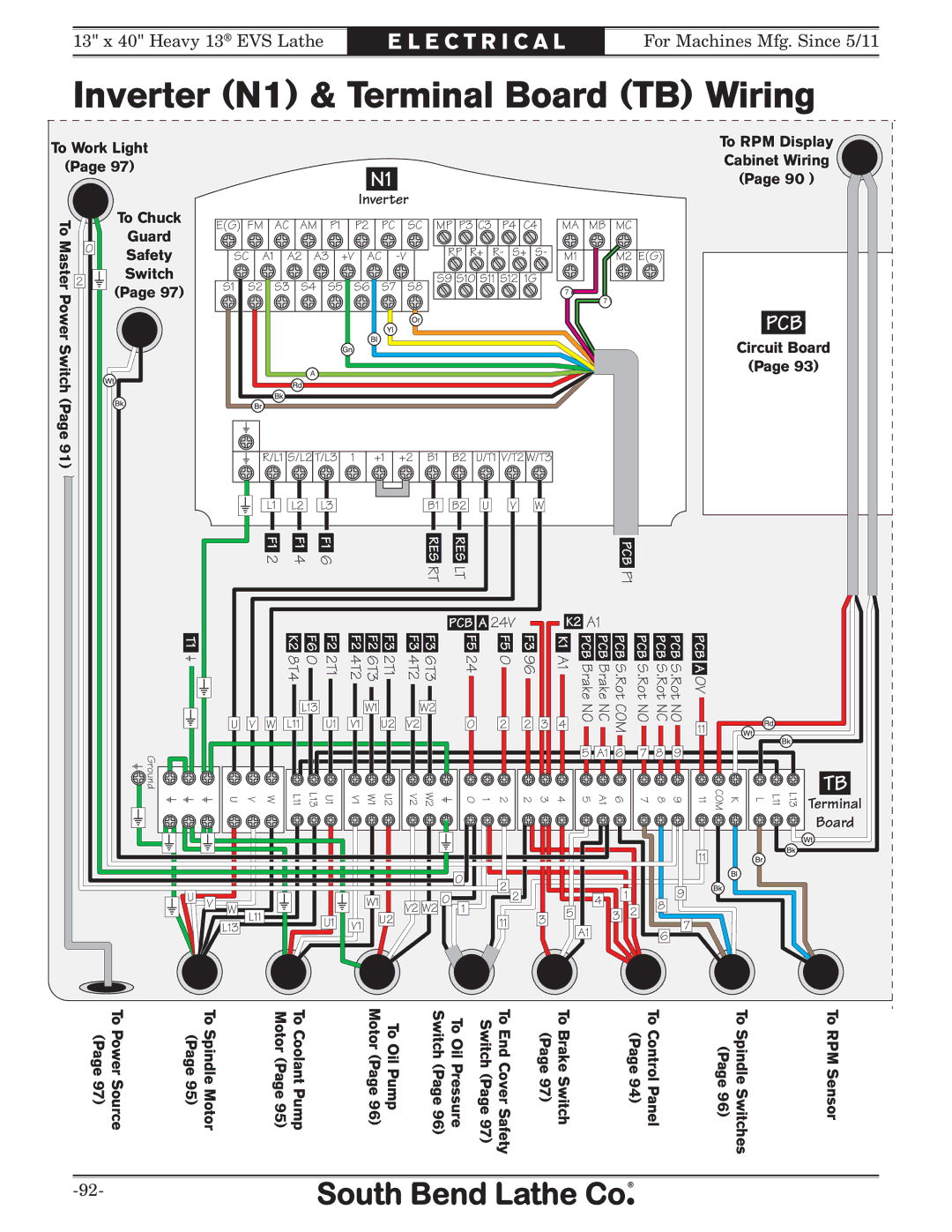
Inverter (N1) & Terminal Board (TB) Wiring

To Work Light

To RPM Display

(Page 97)

Cabinet Wiring


N1


(Page 90 )


To Chuck


Inverter


To


E(G) FM

AC

AM

P1


P2

PC


SC

MP P3 C3

P4 C4

MA

MB

MC


Guard


Master

2


S9 S10 S11 S12 1G


Switch


0

Safety


SC

A1

A2

A3

+V

AC

-V


RP

R+

R-

S+

S-

M1


M2 E(G)


Power


(Page 97)


S1

S2

S3

S4

S5

S6

S7


S8


7e


7\


PCB

Switch(Page


Circuit Board


A\


(Page 93)


91)


R/L1 S/L2 T/L3


1

+1


+2

B1

B2

U/T1 V/T2 W/T3


L1


L2


L3


B1

B2

U

V

W


F1 2


F1 4


F1 6


RES

RES


PCB


RT

LT


P1


PCB A 24V


K2 A1


T1


K2 8T4

F6 0

F2 2T1


F2 4T2

F2 6T3

F3 2T1


F3 4T2

F3 6T3


F5 24

F5 0

F3 96


K1 A1

PCB Brake

PCB Brake

PCB S.Rot

PCB S.Rot

PCB S.Rot PCB S.Rot

PCB A 0V


L13


W1


W2


NO

NC

COM

NO

NO NC


U

V


W

L11


U1


V1


U2


V2


0

2

2

3

4

11


Ground


5

A1

6

7

8

9


COM


L L11 L13 Terminal


U

V


W


L11

L13

U1


V1

W1

U2


V2

W2


1 0

2

2

3

4

5

A1

6

7

8

9

11

K


TB


Board


11


0


2


9


U


0


2


4

1


V

W


W1


8


L11


V2 W2

1


3

5


3

2


L13


U1


V1

U2


11


7


A1


6


(Page 97)

To Power Source

(Page 95)

To Spindle Motor


Motor (Page 95)


To Coolant Pump


Motor (Page 96)

To Oil Pump


Switch (Page 96)

To Oil Pressure

Switch (Page 97)

To End Cover Safety


(Page 97)

To Brake Switch


(Page 94)

To Control Panel


(Page 96)

To Spindle Switches

To RPM Sensor


-92-


Page 94
Image 94
Southbend SB1051 owner manual Inverter N1 & Terminal Board TB Wiring, Pcb

SB1051 specifications

The Southbend SB1051 is a highly regarded gas range designed for commercial kitchens, embodying quality and efficiency in its construction and functionalities. This robust cooking appliance is specifically engineered to meet the high demands of professional chefs and food establishments, making it an ideal choice for restaurants, cafes, and catering services.

One of the standout features of the Southbend SB1051 is its powerful cooking capabilities. It boasts a total of five open gas burners, each delivering substantial heat output to ensure quick and consistent cooking results. The burners are designed for durability, featuring cast iron grates that provide excellent heat retention and stability for pots and pans. The heat output is generally rated at 30,000 BTUs per burner, making this range suitable for everything from boiling to sautéing and simmering.

In addition to its burners, the SB1051 integrates an impressive oven system. The range includes a standard oven capable of reaching high temperatures for baking and roasting. This oven is designed with heavy-duty construction and features a sturdy door that can withstand the rigors of daily use. Furthermore, it may come with adjustable racks, providing flexibility in cooking different types of dishes simultaneously.

The Southbend SB1051 places a strong emphasis on safety and ease of use. It includes an electronic ignition system that eliminates the need for matches or manual lighting, reducing the risk of accidents in busy kitchen environments. The range also features convenient heat controls, allowing chefs to adjust the temperature efficiently and precisely. The stainless-steel front and sides not only enhance the body’s durability but also make cleaning and maintenance simpler.

Moreover, this range is engineered with practical ergonomics in mind. Its height and depth are designed to optimize the workflow in the kitchen, ensuring that chefs can work comfortably without straining.

In summary, the Southbend SB1051 gas range stands out for its robust construction, powerful burners, and user-friendly features. With its combination of high-performance cooking technology and safety considerations, it is an exceptional investment for anyone looking to enhance their culinary operations. This range sets a high standard in commercial cooking equipment, delivering efficiency and reliability to meet the demands of any professional kitchen.