GROUNDING INSTRUCTIONS
The machine must be grounded if you are using the external power supply or the battery charger. Grounding provides the path of least resistance for the electric current, thereby reducing the risk of electric shock. The power supply or battery charger must be plugged into an appropriate outlet that is properly installed and grounded in accordance with all local codes and ordinances.
!DANGER
IMPROPER CONNECTION OF THE
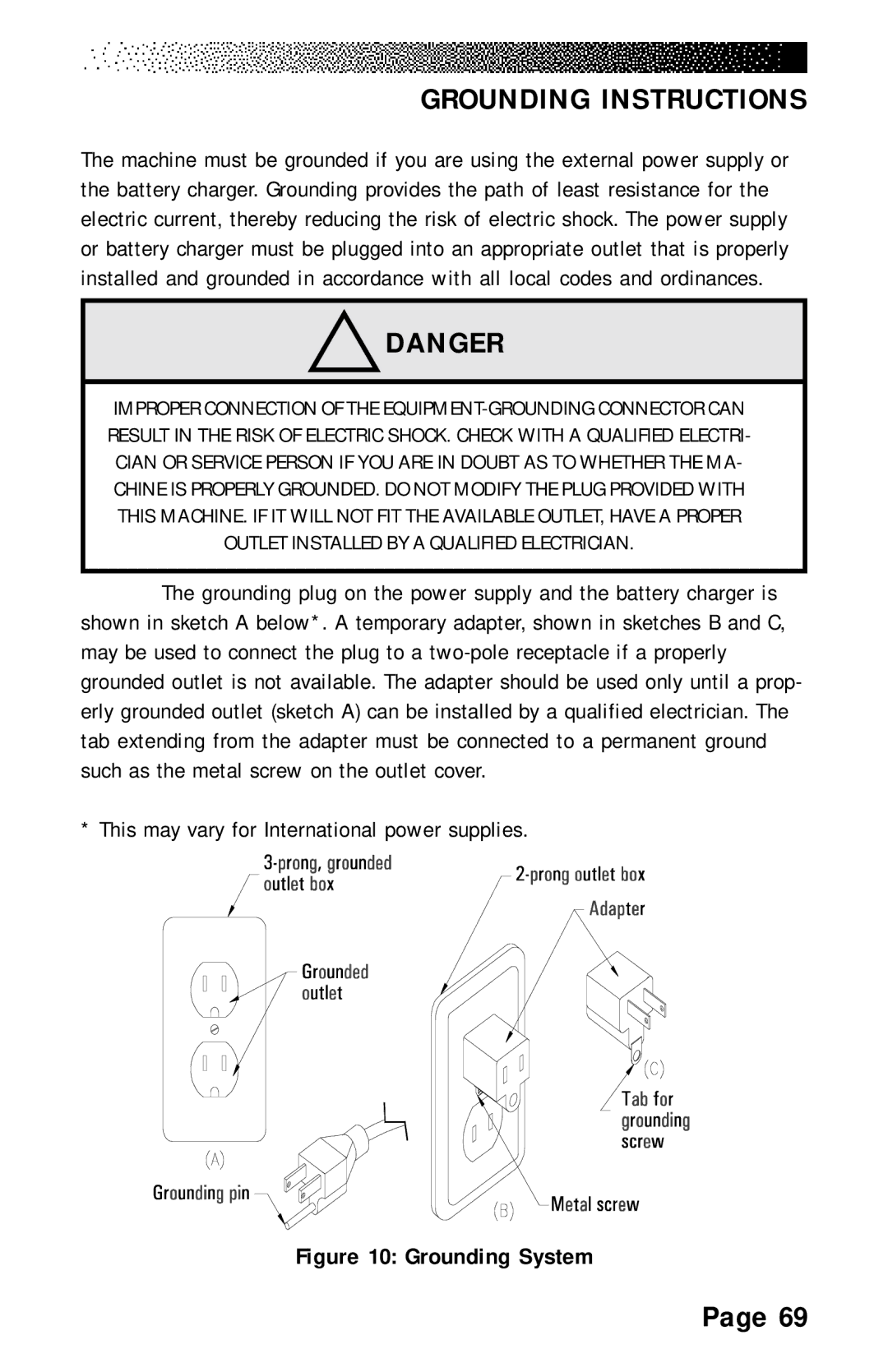
The grounding plug on the power supply and the battery charger is shown in sketch A below*. A temporary adapter, shown in sketches B and C, may be used to connect the plug to a
* This may vary for International power supplies.
Figure 10: Grounding System
Page 69